Frames
CalcpadCE worksheets in this section model plane frames by the direct stiffness method, assembling each frame from joint coordinates, an element table and a list of nodal supports. The local 6×6 element stiffness matrices include axial, bending and shear flexibility, are rotated into the global axes through the transformation \(T\), and are added into the global matrix \(K\) that is solved by Cholesky decomposition for the joint displacements.
A single-storey frame with prismatic members treats two arbitrary cross-sections (a circular and a rectangular one) and shows how the section properties — area, centroid, second moment of area and shear area — are computed by integrating \(b(z)\) over the section depth.
A tapered-section variant lets the width and height vary linearly along each element, so the stiffness coefficients themselves become integrals along \(x\), evaluated numerically with Area.
A five-storey three-bay reinforced concrete frame builds the geometry programmatically, derives the dead, live and self-weight loads from material unit weights, and uses T-shaped beam sections with an effective flange width.
A small SVG drawing library, svg_drawing.cpd, is included by each worksheet to render the structural scheme — joints, members, supports, loads and dimensions — directly into the report.
Frame
Plane frame analysis with prismatic arbitrary cross-sections, assembling local 6x6 stiffness matrices with axial, bending and shear contributions and solving the global system by Cholesky decomposition.
#include svg_drawing.cpd
'<h4>Joint coordinates - xJ; yJ</h4>
#hide
#deg
δz = 10^-12
Precision = 10^-9
x_J = [0; 0; 8; 16; 16]*m
y_J = [0; 8; 10; 8; 0]*m
#show
x_J','y_J
n_J = len(x_J)
'<h4>Elements - [J1; J2]</h4>
#hide
e_J = [1; 2|2; 3|3; 4|4; 5]
#show
transp(e_J)', 'n_E = n_rows(e_J)
'Element endpoint coordinates
x_1(e) = x_J.e_J.(e; 1)','y_1(e) = y_J.e_J.(e; 1)', ' _
x_2(e) = x_J.e_J.(e; 2)','y_2(e) = y_J.e_J.(e; 2)
'Element length - 'l(e) = sqrt((x_2(e) - x_1(e))^2 + (y_2(e) - y_1(e))^2)
'Element direction
c(e) = (x_2(e) - x_1(e))/l(e)','s(e) = (y_2(e) - y_1(e))/l(e)
'Transformation matrix
'Diagonal 3x3 block -'t(e) = [c(e); s(e); 0| - s(e); c(e); 0|0; 0; 1]
'Generation of the full transformation matrix
T(e) = add(t(e); add(t(e); matrix(6; 6); 1; 1); 4; 4)
'<h4>Supports - [Joint; cx; cy; cr]</h4>
#hide
c = [1; 10^20kN/m; 10^20kN/m; 0kNm|5; 10^20kN/m; 10^20kN/m; 10^20kNm]
#show
c
n_c = n_rows(c)
'<h4>Loads - [Element, qx, qy]</h4>
#hide
q = [1; 10kN/m; 0kN/m|2; 0kN/m; -20kN/m|3; 0kN/m; -10kN/m]
n_q = n_rows(q)
q_x = vector(n_E)*kN/m
q_y = vector(n_E)*kN/m
$Repeat{q_x.(q.(i; 1)) = q_x.(q.(i; 1)) + q.(i; 2) @ i = 1 : n_q}
$Repeat{q_y.(q.(i; 1)) = q_y.(q.(i; 1)) + q.(i; 3) @ i = 1 : n_q}
#show
q
'Load values on elements
q_x
q_y
'<h4>Scheme of the structure</h4>
#hide
w = max(x_J)
h = max(y_J)
W = 240
H = h*W/w
k = W/w
#def svg$ = '<svg viewbox="'-3m*k' '-2m*k' '(w + 6m)*k' '(h + 4m)*k'" xmlns="http://www.w3.org/2000/svg" version="1.1" style="font-family: Georgia Pro; font-size:8px; width:'W + 150'pt; height:'H + 200*H/W'pt">
#def thin_style$ = style = "stroke:green; stroke-width:1; fill:none"
#def thick_style$ = style = "stroke:green; stroke-width:2; fill:none"
k_q = m/kN
#show
#val
svg$
#for i = 1 : n_E
    #hide
    x1 = x_1(i)*k
    y1 = (h - y_1(i))*k
    x2 = x_2(i)*k
    y2 = (h - y_2(i))*k
    q_xi = q_x.i
    q_yi = q_y.i
    α = atan2(c(i); s(i))
    #if α ≥ 135
        α = α - 180
    #end if
    #if α < -45
        α = α + 180
    #else if α < 0
        α = 360 + α
    #end if
    #if q_xi ≠ 0kN/m
        #hide
        x3 = x2 - q_xi*k_q','y3 = y2
        x4 = x1 - q_xi*k_q','y4 = y1
        x = (x3 + x4)/2 - 5*sign(q_xi)
        y = (y3 + y4)/2
        #show
        '<polygon points="'x1','y1' 'x2','y2' 'x3','y3' 'x4','y4'" style="stroke:magenta; stroke-width:1; stroke-opacity:0.3; fill:magenta; fill-opacity:0.1;" />
        text$(x;y;α;qx='abs(q_xi)')
    #end if
    #if q_yi ≠ 0kN/m
        #hide
        x3 = x2','y3 = y2 + q_yi*k_q
        x4 = x1','y4 = y1 + q_yi*k_q
        x = (x3 + x4)/2
        y = (y3 + y4)/2 + 5*sign(q_yi)
        #show
        '<polygon points="'x1','y1' 'x2','y2' 'x3','y3' 'x4','y4'" style="stroke:dodgerblue; stroke-width:1; stroke-opacity:0.4; fill:dodgerblue; fill-opacity:0.15;" />
        text$(x;y;α;qy='abs(q_yi)')
    #end if
    #show
    line$(x1; y1; x2; y2; main_style$)
#loop
'<g id="frame">
#for i = 1 : n_E
    #hide
    x1 = x_1(i)*k
    y1 = (h - y_1(i))*k
    x2 = x_2(i)*k
    y2 = (h - y_2(i))*k
    #show
    line$(x1; y1; x2; y2; main_style$)
#loop
#for i = 1 : n_c
    #hide
    j = c.(i; 1)
    x1 = x_J.j*k
    y1 = (h - y_J.j)*k
    δ = 10*sign(x1 - w/2*k)
    x2 = x1 - δ
    y2 = y1 - abs(δ)
    x3 = x1 + δ
    y3 = y1 + abs(δ)
    #show
    #if c.(i; 2) ≠ 0kN/m
        #if c.(i; 3) ≠ 0kN/m
            #if c.(i; 4) ≠ 0kNm
                line$(x1; y1; x1; y3; thin_style$)
                line$(x2; y3; x3; y3; thick_style$)
            #else
                line$(x2; y3; x3; y3; thick_style$)
                line$(x2; y3; x1; y1; thin_style$)
                line$(x3; y3; x1; y1; thin_style$)
            #end if
        #else
            #if c.(i; 4) ≠ 0kNm
                line$(x1; y1; x2; y1; thin_style$)
                line$(x2; y2; x2; y3; thick_style$)
                line$(x2 - δ/2; y2; x2 - δ/2; y3; thick_style$)
            #else
                line$(x2; y2; x1; y1; thin_style$)
                line$(x2; y3; x1; y1; thin_style$)
                line$(x2; y2; x2; y3; thin_style$)
                line$(x2 - δ/2; y2; x2 - δ/2; y3; thick_style$)
            #end if
        #end if
    #else
        #if c.(i; 3) ≠ 0kN/m
            #if c.(i; 4) ≠ 0kNm
                line$(x1; y1; x1; y3; thin_style$)
                line$(x2; y3; x3; y3; thick_style$)
                line$(x2; y3 + abs(δ)/2; x3; y3 + abs(δ)/2; thick_style$)
            #else
                line$(x2; y3; x3; y3; thin_style$)
                line$(x2; y3; x1; y1; thin_style$)
                line$(x3; y3; x1; y1; thin_style$)
                line$(x2; y3 + abs(δ)/2; x3; y3 + abs(δ)/2; thick_style$)
            #end if
        #else
            line$(x2; y2; x3; y3; thick_style$)
        #end if
    #end if
#loop
'</g>
#for i = 1 : n_E
    #hide
    x = (x_1(i) + x_2(i))*k/2
    y = (h - (y_1(i) + y_2(i))/2)*k
    #show
    texth$(x + 0.8m*sign(W/2 - x)*k; y + 0.6m*k; e'i')
#loop
#for i = 1 : n_J
    point$(x_J.i*k; (h - y_J.i)*k; point_style$)
    texth$((x_J.i - 0.7m*sign(w/2 - x_J.i))*k; (h - y_J.i - 0.4m)*k; J'i')
#loop
dimv$((w + 2m)*k; (h - y_J.4)*k; h*k; 'y_J.4')
dimv$((w + 2m)*k; 0; (h - y_J.4)*k; 'h - y_J.4')
dimh$(0; w*k; (h + 1.5m)*k; 'w')
'</svg>
#equ
'<h4>Materials</h4>
'Modules of elasticity -'E = [45; 35]*GPa
'Poisson coefficients -'ν = [0.2; 0.2]
'Shear modules -'G = E/(2*(1 + ν))
'Assignments on elements -'e_M = [1; 2; 2; 1]
'<h4>Cross-sections</h4>
#hide
b = vector(2)','h = vector(2)
#show
'Section S1 -'h.1 = 500mm'- circular - 'b_C(z) = 2*sqrt((h.1/2)^2 - (z - h.1/2)^2)
'Section S2 -'b.2 = 250mm','h.2 = 700mm'- rectangular -'b_R(z) = b.2
'General representation -'b(z; s) = take(s; b_C(z); b_R(z))
'<h4>Cross section properties</h4>
'Equations
'Area -'A(s) = $Integral{b(z; s) @ z = 0mm : h.s}
'First moment of area -'S(s) = $Integral{b(z; s)*z @ z = 0mm : h.s}|cm^3
'Centroid -'z_c(s) = S(s)/A(s)|mm
'Second moment of area -'I(s) = $Integral{b(z; s)*(z - z_c(s))^2 @ z = 0mm : h.s}
'First moment of area below z -'S_1(z; s) = $Integral{b(ζ; s)*(z_c(s) - ζ) @ ζ = 0mm : z}
'Shear area -'A_s(s) = I(s)^2/$Integral{S_1(z; s)^2/b(z; s) @ z = 0mm : h.s}
'Calculated results
'Centroids -'z_c = [z_c(1); z_c(2)]
'Areas -'A = [A(1); A(2)]
'Shear areas -'A_s = [A_s(1); A_s(2)]
'Second moments of area -'I = [I(1); I(2)]
'Assignments on elements -'e_S = [1; 2; 2; 1]
'<h4>Element stiffness matrix</h4>
'Elastic properties for element "e"
EA_e(e) = E.e_M.e*A.e_S.e', 'EI_e(e) = E.e_M.e*I.e_S.e', ' _
GA_s(e) = G.e_M.e*A_s.e_S.e
k_s(e) = 12*EI_e(e)/(GA_s(e)*l(e)^2)', ' _
α(e) = EA_e(e)/l(e)','β(e) = EI_e(e)/(l(e)^3*(1 + k_s(e)))
'Stiffness matrix coefficients for element "e"
k_11(e) = α(e)*(m/kN)','k_22(e) = 12*β(e)*(m/kN)','k_23(e) = 6*β(e)*l(e)*(1/kN)
k_33(e) = (4 + k_s(e))*β(e)*l(e)^2*(1/kNm)',' _
k_36(e) = (2 - k_s(e))*β(e)*l(e)^2*(1/kNm)
'Assembling the 3x3 stiffness matrix blocks for element "e"
k_ii(e) = [k_11(e)|0; k_22(e); k_23(e)|0; k_23(e); k_33(e)]
k_ij(e) = [-k_11(e)|0; -k_22(e); k_23(e)|0; -k_23(e); k_36(e)]
k_ji(e) = transp(k_ij(e))
k_jj(e) = [k_11(e)|0; k_22(e); -k_23(e)|0; -k_23(e); k_33(e)]
'Full element stiffness matrix
k_E(e) = stack(augment(k_ii(e); k_ij(e)); augment(k_ji(e); k_jj(e)))
'Stiffness matrices obtained in local coordinates
k_E(1)
k_E(2)
'Stiffness matrices obtained in global coordinates
transp(T(1))*k_E(1)*T(1)
transp(T(2))*k_E(2)*T(2)
'<h4>Global stiffness matrix</h4>
#hide
K = symmetric(3*n_J)
'Add element stiffness matrices
#for e = 1 : n_E
    i = 3*e_J.(e; 1) - 2','j = 3*e_J.(e; 2) - 2
    t = t(e)','tT = transp(t)
    add(tT*k_ii(e)*t; K; i; i)
    #if j > i
        add(tT*k_ij(e)*t; K; i; j)
    #else
        add(tT*k_ji(e)*t; K; j; i)
    #end if
    add(tT*k_jj(e)*t; K; j; j)
#loop
'Add supports
#for i = 1 : n_c
    j = 3*c.(i; 1) - 2
    add(vec2diag(last(row(c; i); 3)/[kN/m; kN/m; kNm]); K; j; j)
#loop
#show
K
'<h4>Element load vector</h4>
'Lateral load in local CS -'q_E(e) = -q_x.e*s(e) + q_y.e*c(e)
'Axial load in local CS -'n_E(e) = q_x.e*c(e) + q_y.e*s(e)
'Equivalent loads at element endpoints
F_Ex(e) = q_x.e*l(e)/2*(1/kN)','F_Ey(e) = q_y.e*l(e)/2*(1/kN)' ,' _
M_E(e) = q_E(e)*l(e)^2/12*(1/kNm)
'Load vector -'F_E(e) = [F_Ex(e); F_Ey(e); M_E(e); F_Ex(e); F_Ey(e); -M_E(e)]
#novar
'Results for elements
#for e = 1 : n_E
    'Element Е'e' -'F_E(e)
#loop
#varsub
'<h4>Global load vector</h4>
#hide
F = vector(3*n_J)
#for i = 1 : n_q
    e = q.(i; 1)
    #for jj = 1 : 2
        j = 3*e_J.(e; jj) - 3
        F.(j + 1) = F.(j + 1) + take(3*jj - 2; F_E(e))
        F.(j + 2) = F.(j + 2) + take(3*jj - 1; F_E(e))
        F.(j + 3) = F.(j + 3) + take(3*jj; F_E(e))
    #loop
#loop
#show
F
'<h4>Results</h4>
'<p><strong>Solution of the system of equations by Cholesky decomposition</strong></p>
Z = clsolve(K; F)
'<p><strong>Joint displacements</strong></p>
z_J(j) = slice(Z; 3*j - 2; 3*j)
z(j) = round(z_J(j)/δz)*δz*1000*[mm; mm; 1]
#novar
#for j = 1 : n_J
    z(j)
#loop
#varsub
'<p><strong>Support reactions</strong></p>
r(i) = row(c; i)','j(i) = take(1; r(i))
R(i) = -z_J(j(i))*[m; m; 1]*last(r(i); 3)
#novar
#for i = 1 : n_c
    #val
    '<p>Joint <b>J'j(i)' -
    #equ
    '</b>'R(i)'</p>
#loop
#varsub
'<p><strong>Element end forces</strong></p>
z_E(e) = [z_J(e_J.(e; 1)); z_J(e_J.(e; 2))]
R_E(e) = col(k_E(e)*T(e)*z_E(e) - T(e)*F_E(e); 1)*[1; 1; m; 1; 1; m]*kN
#novar
#for e = 1 : n_E
    R_E(e)
#loop
#varsub
'<p><strong>Element internal forces</strong></p>
N(e; x) = -take(1; R_E(e)) - n_E(e)*x', ' _
Q(e; x) = take(2; R_E(e)) + q_E(e)*x
M(e; x) = -take(3; R_E(e)) + take(2; R_E(e))*x + q_E(e)*x^2/2
#hide
R(e; x; i) = take(i; N(e; x); Q(e; x); M(e; x))
w = max(x_J)
h = max(y_J)
W = 240
H = h*W/w
k = W/w
#def red_style$ = style = "stroke:red; stroke-width:1; fill:red"
#deg
#for i = 1 : 3
    #hide
    sgn = take(i; 1; 1; -1)
    unit = take(i; kN; kN; kNm)
    tol = 0.01*unit
    R = vector_hp(n_E)*unit
    $Repeat{R.e = $Sup{R(e; x; i) @ x = 0m : l(e)} @ e = 1 : n_E}
    R_max = max(R)
    $Repeat{R.e = abs($Inf{R(e; x; i) @ x = 0m : l(e)}) @ e = 1 : n_E}
    R_max = max(max(R); R_max)
    k_R = sgn*1m*k/R_max
    #show
    #if i ≡ 1
        '<p><strong>Axial forces diagram, kN</strong></p>
    #else if i ≡ 2
        '<p><strong>Shear forces diagram, kN</strong></p>
    #else
        '<p><strong>Bending moments diagram, kNm</strong></p>
    #end if
    #val
    svg$
    '<use href="#frame"/>
    #for e = 1 : n_E
        #hide
        x1 = x_1(e)*k
        y1 = (h - y_1(e))*k
        x2 = x_2(e)*k
        y2 = (h - y_2(e))*k
        c_e = c(e)
        s_e = s(e)
        l_e = l(e)
        st = l_e/10
        xd2 = x1
        yd2 = y1
        #show
        #for j = 0 : 10
            #hide
            xd1 = xd2
            yd1 = yd2
            x = j*st*k
            v = R(e; j*st; i)
            y = v*k_R
            xd2 = x1 + x*c_e - y*s_e
            yd2 = y1 - x*s_e - y*c_e
            α = 90 + atan2(c_e; s_e)
            #if α ≥ 135
                α = α - 180
            #end if
            #if α < -45
                α = α + 180
            #else if α < 0
                α = 360 + α
            #end if
            d = -15*sign(v*sgn)
            #show
            line$(xd1; yd1; xd2; yd2; red_style$)
            #if (j ≡ 0 ∨ j ≡ 10) ∧ abs(v) > tol
                text$(xd2 + s_e*d; yd2 + d*c_e; α; 'v')
            #end if
            line$(xd1; yd1; xd2; yd2; red_style$)
        #loop
        #hide
        xd1 = x2
        yd1 = y2
        #show
        line$(xd1; yd1; xd2; yd2; red_style$)
    #loop
    '</svg>
#loop
#equ
'<p><strong>Deformed shape</strong></p>
'Shape function in relative coordinates ξ = x/l (with account to shear deflections)
Φ_1(e; ξ) = 1/(1 + k_s(e))*(1 + k_s(e) - k_s(e)*ξ - 3*ξ^2 + 2*ξ^3)
Φ_2(e; ξ) = ξ*l(e)*m^-1/(1 + k_s(e))*(1 + k_s(e)/2 - (2 + k_s(e)/2)*ξ + ξ^2)
Φ_3(e; ξ) = ξ/(1 + k_s(e))*(k_s(e) + 3*ξ - 2*ξ^2)
Φ_4(e; ξ) = ξ*l(e)*m^-1/(1 + k_s(e))*(-k_s(e)/2 - (1 - k_s(e)/2)*ξ + ξ^2)
'Element endpoint displacements and rotations
z_E,loc(e) = T(e)*z_E(e)
u_1(e) = take(1; z_E,loc(e))','v_1(e) = take(2; z_E,loc(e))','φ_1(e) = take(3; z_E,loc(e))
u_2(e) = take(4; z_E,loc(e))','v_2(e) = take(5; z_E,loc(e))','φ_2(e) = take(6; z_E,loc(e))
'Displacement functions
u(e; ξ) = u_1(e)*(1 - ξ) + u_2(e)*ξ + n_E(e)*.m/EA_e(e)*ξ*(1 - ξ)
v(e; ξ) = v_1(e)*Φ_1(e; ξ) + φ_1(e)*Φ_2(e; ξ) + v_2(e)*Φ_3(e; ξ) + φ_2(e)*Φ_4(e; ξ) + q_E(e)*l(e)^4/(24*EI_e(e))*(ξ^2*(1 - ξ)^2/.m) + q_E(e)*l(e)^2/(2*GA_s(e))*(ξ*(1 - ξ)/.m)
'Deformed shape, mm
#val
#hide
tol = 0.00001
k_R = 10/max(abs(Z))
#show
svg$
'<use href="#frame" style="opacity:0.4;"/>
#for e = 1 : n_E
    #hide
    x1 = x_1(e)*k
    y1 = (h - y_1(e))*k
    x2 = x_2(e)*k
    y2 = (h - y_2(e))*k
    c_e = c(e)
    s_e = s(e)
    l_e = l(e)
    u = u(e; 0)
    v = v(e; 0)
    x = u*k_R
    y = v*k_R
    xd2 = x1 + x*c_e - y*s_e
    yd2 = y1 - x*s_e - y*c_e
    #show
    #for j = 0 : 10
        #hide
        xd1 = xd2
        yd1 = yd2
        ξ = j/10
        u = u(e; ξ)
        v = v(e; ξ)
        x = ξ*l_e*k + u*k_R
        y = v*k_R
        xd2 = x1 + x*c_e - y*s_e
        yd2 = y1 - x*s_e - y*c_e
        d = -15*sign(v)
        #show
        line$(xd1; yd1; xd2; yd2; red_style$)
    #loop
#loop
#for j = 1 : n_J
    #hide
    z_J = z_J(j)
    u = z_J.1
    v = z_J.2
    x = x_J.j*k + u*k_R
    y = (h - y_J.j)*k - v*k_R
    dx = 15*sign(u)
    dy = -15*sign(v)
    #show
    #if abs(u) > tol
        texth$(x + dx; y; 'u*1000')
    #end if
    #if abs(v) > tol
        textv$(x; y + dy; 'v*1000')
    #end if
#loop
'</svg>
#equ
⃗xJ = [0 m 0 m 8 m 16 m 16 m] , ⃗yJ = [0 m 8 m 10 m 8 m 0 m]
nJ = len ( ⃗xJ ) = 5
transp ( eJ ) = 1234 2345 , nE = nrows ( eJ ) = 4
Element endpoint coordinates
x1 ( e ) = ⃗xJ.eJ.e,1 , y1 ( e ) = ⃗yJ.eJ.e,1 , x2 ( e ) = ⃗xJ.eJ.e,2 , y2 ( e ) = ⃗yJ.eJ.e,2
Element length - l ( e ) = √ ( x2 ( e ) − x1 ( e ) ) 2 + ( y2 ( e ) − y1 ( e ) ) 2
Element direction
c ( e ) = x2 ( e ) − x1 ( e ) l ( e ) , s ( e ) = y2 ( e ) − y1 ( e ) l ( e )
Transformation matrix
Diagonal 3x3 block - t ( e ) = [c ( e ) ; s ( e ) ; 0 | -s ( e ) ; c ( e ) ; 0 | 0; 0; 1]
Generation of the full transformation matrix
T ( e ) = add ( t ( e ) ; add ( t ( e ) ; matrix ( 6; 6 ) ; 1; 1 ) ; 4; 4 )
c = 11020 kN ∕ m1020 kN ∕ m0 kNm 51020 kN ∕ m1020 kN ∕ m1020 kNm
nc = nrows ( c ) = 2
q = 110 kN ∕ m0 kN ∕ m 20 kN ∕ m-20 kN ∕ m 30 kN ∕ m-10 kN ∕ m
Load values on elements
⃗qx = [10 kN ∕ m 0 kN ∕ m 0 kN ∕ m 0 kN ∕ m]
⃗qy = [0 kN ∕ m -20 kN ∕ m -10 kN ∕ m 0 kN ∕ m]
Modules of elasticity - ⃗E = [45; 35] · GPa = [45 GPa 35 GPa]
Poisson coefficients - ⃗ν = [0.2; 0.2] = [0.2 0.2]
Shear modules - ⃗G = ⃗E2 · ( 1 + ⃗ν ) = [18.75 GPa 14.58 GPa]
Assignments on elements - ⃗eM = [1; 2; 2; 1] = [1 2 2 1]
Section S1 - ⃗h1 = 500 mm - circular - bC ( z ) = 2 · (⃗h12)2 − (z − ⃗h12)2
Section S2 - ⃗b2 = 250 mm , ⃗h2 = 700 mm - rectangular - bR ( z ) = ⃗b2
General representation - b ( z; s ) = take ( s; bC ( z ) ; bR ( z ) )
Equations
Area - A ( s ) = ⃗hs∫0 mm b ( z; s ) dz
First moment of area - S ( s ) = ⃗hs∫0 mm b ( z; s ) · z dz
Centroid - zc ( s ) = S ( s ) A ( s )
Second moment of area - I ( s ) = ⃗hs∫0 mm b ( z; s ) · ( z − zc ( s ) ) 2 dz
First moment of area below z - S1 ( z; s ) = z∫0 mm b ( ζ; s ) · ( zc ( s ) − ζ ) dζ
Shear area - As ( s ) = I ( s ) 2 ⃗hs∫0 mm S1 ( z; s ) 2b ( z; s ) dz
Calculated results
Centroids - ⃗zc = [zc ( 1 ) ; zc ( 2 ) ] = [250 mm 350 mm]
Areas - ⃗A = [A ( 1 ) ; A ( 2 ) ] = [196350 mm2 175000 mm2]
Shear areas - ⃗As = [As ( 1 ) ; As ( 2 ) ] = [176715 mm2 145833 mm2]
Second moments of area - ⃗I = [I ( 1 ) ; I ( 2 ) ] = [3067961576 mm4 7145833333 mm4]
Assignments on elements - ⃗eS = [1; 2; 2; 1] = [1 2 2 1]
Elastic properties for element "e"
EAe ( e ) = ⃗E⃗eM.e · ⃗AeS.e , EIe ( e ) = ⃗E⃗eM.e · ⃗IeS.e , GAs ( e ) = ⃗G⃗eM.e · ⃗As.eS.e
ks ( e ) = 12 · EIe ( e ) GAs ( e ) · l ( e ) 2 , α ( e ) = EAe ( e ) l ( e ) , β ( e ) = EIe ( e ) l ( e ) 3 · ( 1 + ks ( e ) )
Stiffness matrix coefficients for element "e"
k11 ( e ) = α ( e ) · mkN , k22 ( e ) = 12 · β ( e ) · mkN , k23 ( e ) = 6 · β ( e ) · l ( e ) · 1kN
k33 ( e ) = ( 4 + ks ( e ) ) · β ( e ) · l ( e ) 2 · 1kNm , k36 ( e ) = ( 2 − ks ( e ) ) · β ( e ) · l ( e ) 2 · 1kNm
Assembling the 3x3 stiffness matrix blocks for element "e"
kii ( e ) = [k11 ( e ) | 0; k22 ( e ) ; k23 ( e ) | 0; k23 ( e ) ; k33 ( e ) ]
kij ( e ) = [-k11 ( e ) | 0; -k22 ( e ) ; k23 ( e ) | 0; -k23 ( e ) ; k36 ( e ) ]
kji ( e ) = transp ( kij ( e ) )
kjj ( e ) = [k11 ( e ) | 0; k22 ( e ) ; -k23 ( e ) | 0; -k23 ( e ) ; k33 ( e ) ]
Full element stiffness matrix
kE ( e ) = stack ( augment ( kii ( e ) ; kij ( e ) ) ; augment ( kji ( e ) ; kjj ( e ) ) )
Stiffness matrices obtained in local coordinates
kE ( 1 ) = 110446600-110446600 03210.6612842.60-3210.6612842.6 012842.668627.80-12842.634113.2 -110446600110446600 0-3210.66-12842.603210.66-12842.6 012842.634113.20-12842.668627.8
kE ( 2 ) = 74276500-74276500 05243.4621619.30-5243.4621619.3 021619.31194680-21619.358809.3 -7427650074276500 0-5243.46-21619.305243.46-21619.3 021619.358809.30-21619.3119468
Stiffness matrices obtained in global coordinates
transp ( T ( 1 ) ) · kE ( 1 ) · T ( 1 ) = 3210.660-12842.6-3210.660-12842.6 0110446600-11044660 -12842.6068627.812842.6034113.2 -3210.66012842.63210.66012842.6 0-11044660011044660 -12842.6034113.212842.6068627.8
transp ( T ( 2 ) ) · kE ( 2 ) · T ( 2 ) = 699382173535-5243.46-699382-173535-5243.46 17353548627.120973.8-173535-48627.120973.8 -5243.4620973.81194685243.46-20973.858809.3 -699382-1735355243.466993821735355243.46 -173535-48627.1-20973.817353548627.1-20973.8 -5243.4620973.858809.35243.46-20973.8119468
K = 10200-12842.6-3210.660-12842.6000000000 0102000-11044660000000000 -12842.6068627.812842.6034113.2000000000 -3210.66012842.67025921735357599.17-699382-173535-5243.46000000 0-11044660173535115309320973.8-173535-48627.120973.8000000 -12842.6034113.27599.1720973.81880965243.46-20973.858809.3000000 000-699382-1735355243.461398763010486.9-6993821735355243.46000 000-173535-48627.1-20973.8097254.20173535-48627.120973.8000 000-5243.4620973.858809.310486.90238937-5243.46-20973.858809.3000 000000-699382173535-5243.46702592-1735357599.17-3210.66012842.6 000000173535-48627.1-20973.8-1735351153093-20973.80-11044660 0000005243.4620973.858809.37599.17-20973.8188096-12842.6034113.2 000000000-3210.660-12842.610200-12842.6 0000000000-11044660010200 00000000012842.6034113.2-12842.601020
Lateral load in local CS - qE ( e ) = -⃗qx.e · s ( e ) + ⃗qy.e · c ( e )
Axial load in local CS - nE ( e ) = ⃗qx.e · c ( e ) + ⃗qy.e · s ( e )
Equivalent loads at element endpoints
FEx ( e ) = ⃗qx.e · l ( e ) 2 · 1kN , FEy ( e ) = ⃗qy.e · l ( e ) 2 · 1kN , ME ( e ) = qE ( e ) · l ( e ) 212 · 1kNm
Load vector - FE ( e ) = [FEx ( e ) ; FEy ( e ) ; ME ( e ) ; FEx ( e ) ; FEy ( e ) ; -ME ( e ) ]
Results for elements
Element Е 1 - FE ( 1 ) = [40 0 -53.33 40 0 53.33]
Element Е 2 - FE ( 2 ) = [0 -82.46 -109.95 0 -82.46 109.95]
Element Е 3 - FE ( 3 ) = [0 -41.23 -54.97 0 -41.23 54.97]
Element Е 4 - FE ( 4 ) = [0 0 0 0 0 0]
⃗F = [40 0 -53.33 40 -82.46 -56.62 0 -123.69 54.97 0 -41.23 54.97 0 0 0]
Solution of the system of equations by Cholesky decomposition
⃗Z = clsolve ( K; ⃗F ) = [0 0 -0.000928 0.00809 -0.000126 -0.00274 0.0119 -0.0157 0.000699 0.0157 -9.84×10⁻⁵ 0.000846 0 0 0]
Joint displacements
zJ ( j ) = slice ( ⃗Z; 3 · j − 2; 3 · j )
z ( j ) = round(zJ ( j ) δz) · δz · 1000 · [mm; mm; 1]
z ( 1 ) = [0 mm 0 mm -0.928]
z ( 2 ) = [8.09 mm -0.126 mm -2.74]
z ( 3 ) = [11.88 mm -15.67 mm 0.699]
z ( 4 ) = [15.67 mm -0.0984 mm 0.846]
z ( 5 ) = [0 mm 0 mm 0]
Support reactions
r ( i ) = row ( c; i ) , j ( i ) = take ( 1; r ( i ) )
R ( i ) = -zJ ( j ( i ) ) · [m; m; 1] · last ( r ( i ) ; 3 )
Joint J1 - R ( 1 ) = [-18.84 kN 138.69 kN 0 kNm]
Joint J5 - R ( 2 ) = [-61.16 kN 108.7 kN 230.05 kNm]
Element end forces
zE ( e ) = [zJ ( eJ.e,1 ) ; zJ ( eJ.e,2 ) ]
RE ( e ) = col ( kE ( e ) · T ( e ) · zE ( e ) − T ( e ) · FE ( e ) ; 1 ) · [1; 1; m; 1; 1; m] · kN
RE ( 1 ) = [138.69 kN 18.84 kN -1.42×10⁻¹⁴ kNm -138.69 kN 61.16 kN -169.29 kNm]
RE ( 2 ) = [92.97 kN 119.71 kN 169.29 kNm -52.97 kN 40.29 kN 158.18 kNm]
RE ( 3 ) = [65.7 kN -10.62 kN -158.18 kNm -85.7 kN 90.62 kN -259.24 kNm]
RE ( 4 ) = [108.7 kN 61.16 kN 259.24 kNm -108.7 kN -61.16 kN 230.05 kNm]
Element internal forces
N ( e; x ) = -take ( 1; RE ( e ) ) − nE ( e ) · x , Q ( e; x ) = take ( 2; RE ( e ) ) + qE ( e ) · x
M ( e; x ) = -take ( 3; RE ( e ) ) + take ( 2; RE ( e ) ) · x + qE ( e ) · x22
Axial forces diagram, kN
Shear forces diagram, kN
Bending moments diagram, kNm
Deformed shape
Shape function in relative coordinates ξ = x/l (with account to shear deflections)
Φ1 ( e; ξ ) = 11 + ks ( e ) · ( 1 + ks ( e ) − ks ( e ) · ξ − 3 · ξ2 + 2 · ξ3 )
Φ2 ( e; ξ ) = ξ · l ( e ) · m-11 + ks ( e ) · (1 + ks ( e ) 2 − (2 + ks ( e ) 2) · ξ + ξ2)
Φ3 ( e; ξ ) = ξ1 + ks ( e ) · ( ks ( e ) + 3 · ξ − 2 · ξ2 )
Φ4 ( e; ξ ) = ξ · l ( e ) · m-11 + ks ( e ) · (-ks ( e ) 2 − (1 − ks ( e ) 2) · ξ + ξ2)
Element endpoint displacements and rotations
zE,loc ( e ) = T ( e ) · zE ( e )
u1 ( e ) = take ( 1; zE,loc ( e ) ) , v1 ( e ) = take ( 2; zE,loc ( e ) ) , φ1 ( e ) = take ( 3; zE,loc ( e ) )
u2 ( e ) = take ( 4; zE,loc ( e ) ) , v2 ( e ) = take ( 5; zE,loc ( e ) ) , φ2 ( e ) = take ( 6; zE,loc ( e ) )
Displacement functions
u ( e; ξ ) = u1 ( e ) · ( 1 − ξ ) + u2 ( e ) · ξ + nE ( e ) · mEAe ( e ) · ξ · ( 1 − ξ )
v ( e; ξ ) = v1 ( e ) · Φ1 ( e; ξ ) + φ1 ( e ) · Φ2 ( e; ξ ) + v2 ( e ) · Φ3 ( e; ξ ) + φ2 ( e ) · Φ4 ( e; ξ ) + qE ( e ) · l ( e ) 424 · EIe ( e ) · ξ2 · ( 1 − ξ ) 2m + qE ( e ) · l ( e ) 22 · GAs ( e ) · ξ · ( 1 − ξ ) m
Deformed shape, mm
Frame-Var
Plane frame with linearly tapered members: each element stiffness coefficient is obtained by integrating \(1 / EA(x)\), \(x / EI(x)\) and \(1 / GA_Q(x)\) along the element length.
#include svg_drawing.cpd
'<h4>Joint coordinates - xJ; yJ</h4>
#hide
#deg
δz = 10^-12
Precision = 10^-8
x_J = [0; 0; 8; 16; 16]*m
y_J = [0; 8; 10; 8; 0]*m
#show
x_J','y_J
n_J = len(x_J)
'<h4>Elements - [J1; J2]</h4>
#hide
e_J = [1; 2|3; 2|3; 4|5; 4]
#show
transp(e_J)
n_E = n_rows(e_J)
'Element endpoint coordinates
x_1(e) = x_J.e_J.(e; 1)','y_1(e) = y_J.e_J.(e; 1)
x_2(e) = x_J.e_J.(e; 2)','y_2(e) = y_J.e_J.(e; 2)
'Element length - 'l(e) = sqrt((x_2(e) - x_1(e))^2 + (y_2(e) - y_1(e))^2)
'Element directions
c(e) = (x_2(e) - x_1(e))/l(e)','s(e) = (y_2(e) - y_1(e))/l(e)
'Transformation matrix
'Diagonal 3x3 block -'t(e) = [c(e); s(e); 0| - s(e); c(e); 0|0; 0; 1]
'Generation of the full transformation matrix
T(e) = add(t(e); add(t(e); matrix(6; 6); 1; 1); 4; 4)
'<h4>Supports - [Joint; cx; cy; cr]</h4>
#hide
c = [1; 10^20kN/m; 10^20kN/m; 0kNm|5; 10^20kN/m; 10^20kN/m; 10^20kNm]
#show
c
n_c = n_rows(c)
'<h4>Loads - [Element, qx, qy]</h4>
#hide
q = [1; 10kN/m; 0kN/m|2; 0kN/m; -20kN/m|3; 0kN/m; -10kN/m]
n_q = n_rows(q)
q_x = vector(n_E)*kN/m
q_y = vector(n_E)*kN/m
$Repeat{q_x.(q.(i; 1)) = q_x.(q.(i; 1)) + q.(i; 2) @ i = 1 : n_q}
$Repeat{q_y.(q.(i; 1)) = q_y.(q.(i; 1)) + q.(i; 3) @ i = 1 : n_q}
#show
q
'Load values on elements
q_x
q_y
'<h4>Scheme of the structure</h4>
#hide
w = max(x_J)
h = max(y_J)
W = 240
H = h*W/w
k = W/w
#def svg$ = '<svg viewbox="'-3m*k' '-2m*k' '(w + 6m)*k' '(h + 4m)*k'" xmlns="http://www.w3.org/2000/svg" version="1.1" style="font-family: Georgia Pro; font-size:8px; width:'W + 150'pt; height:'H + 200*H/W'pt">
#def thin_style$ = style = "stroke:green; stroke-width:1; fill:none"
#def thick_style$ = style = "stroke:green; stroke-width:2; fill:none"
k_q = m/kN
#show
#val
svg$
#for i = 1 : n_E
    #hide
    x1 = x_1(i)*k
    y1 = (h - y_1(i))*k
    x2 = x_2(i)*k
    y2 = (h - y_2(i))*k
    q_xi = q_x.i
    q_yi = q_y.i
    α = atan2(c(i); s(i))
    #if α ≥ 135
        α = α - 180
    #end if
    #if α < -45
        α = α + 180
    #else if α < 0
        α = 360 + α
    #end if
    #if q_xi ≠ 0kN/m
        #hide
        x3 = x2 - q_xi*k_q','y3 = y2
        x4 = x1 - q_xi*k_q','y4 = y1
        x = (x3 + x4)/2 - 5*sign(q_xi)
        y = (y3 + y4)/2
        #show
        '<polygon points="'x1','y1' 'x2','y2' 'x3','y3' 'x4','y4'" style="stroke:magenta; stroke-width:1; stroke-opacity:0.3; fill:magenta; fill-opacity:0.1;" />
        text$(x;y;α;qx='abs(q_xi)')
    #end if
    #if q_yi ≠ 0kN/m
        #hide
        x3 = x2','y3 = y2 + q_yi*k_q
        x4 = x1','y4 = y1 + q_yi*k_q
        x = (x3 + x4)/2
        y = (y3 + y4)/2 + 5*sign(q_yi)
        #show
        '<polygon points="'x1','y1' 'x2','y2' 'x3','y3' 'x4','y4'" style="stroke:dodgerblue; stroke-width:1; stroke-opacity:0.4; fill:dodgerblue; fill-opacity:0.15;" />
        text$(x;y;α;qy='abs(q_yi)')
    #end if
    #show
    line$(x1; y1; x2; y2; main_style$)
#loop
'<g id="frame">
#for i = 1 : n_E
    #hide
    x1 = x_1(i)*k
    y1 = (h - y_1(i))*k
    x2 = x_2(i)*k
    y2 = (h - y_2(i))*k
    #show
    line$(x1; y1; x2; y2; main_style$)
#loop
#for i = 1 : n_c
    #hide
    j = c.(i; 1)
    x1 = x_J.j*k
    y1 = (h - y_J.j)*k
    δ = w/30*k*sign(x1 - w/2*k)
    x2 = x1 - δ
    y2 = y1 - abs(δ)
    x3 = x1 + δ
    y3 = y1 + abs(δ)
    #show
    #if c.(i; 2) ≠ 0kN/m
        #if c.(i; 3) ≠ 0kN/m
            #if c.(i; 4) ≠ 0kNm
                line$(x1; y1; x1; y3; thin_style$)
                line$(x2; y3; x3; y3; thick_style$)
            #else
                line$(x2; y3; x3; y3; thick_style$)
                line$(x2; y3; x1; y1; thin_style$)
                line$(x3; y3; x1; y1; thin_style$)
            #end if
        #else
            #if c.(i; 4) ≠ 0kNm
                line$(x1; y1; x2; y1; thin_style$)
                line$(x2; y2; x2; y3; thick_style$)
                line$(x2 - δ/2; y2; x2 - δ/2; y3; thick_style$)
            #else
                line$(x2; y2; x1; y1; thin_style$)
                line$(x2; y3; x1; y1; thin_style$)
                line$(x2; y2; x2; y3; thin_style$)
                line$(x2 - δ/2; y2; x2 - δ/2; y3; thick_style$)
            #end if
        #end if
    #else
        #if c.(i; 3) ≠ 0kN/m
            #if c.(i; 4) ≠ 0kNm
                line$(x1; y1; x1; y3; thin_style$)
                line$(x2; y3; x3; y3; thick_style$)
                line$(x2; y3 + abs(δ)/2; x3; y3 + abs(δ)/2; thick_style$)
            #else
                line$(x2; y3; x3; y3; thin_style$)
                line$(x2; y3; x1; y1; thin_style$)
                line$(x3; y3; x1; y1; thin_style$)
                line$(x2; y3 + abs(δ)/2; x3; y3 + abs(δ)/2; thick_style$)
            #end if
        #else
            line$(x2; y2; x3; y3; thick_style$)
        #end if
    #end if
#loop
'</g>
#for i = 1 : n_E
    #hide
    x = (x_1(i) + x_2(i))*k/2
    y = (h - (y_1(i) + y_2(i))/2)*k
    #show
    texth$(x + 0.8m*sign(W/2 - x)*k; y + 0.6m*k; e'i')
#loop
#for i = 1 : n_J
    point$(x_J.i*k; (h - y_J.i)*k; point_style$)
    texth$((x_J.i - 0.7m*sign(w/2 - x_J.i))*k; (h - y_J.i - 0.4m)*k; J'i')
#loop
dimv$((w + 2m)*k; (h - y_J.4)*k; h*k; 'y_J.4')
dimv$((w + 2m)*k; 0; (h - y_J.4)*k; 'h - y_J.4')
dimh$(0; w*k; (h + 1.5m)*k; 'w')
'</svg>
#equ
'<h4>Materials</h4>
'Modules of elasticity -'E = [45; 35]*GPa
'Poisson coefficients -'ν = [0.2; 0.2]
'Shear modules -'G = E/(2*(1 + ν))
'Assignment on elements -'e_M = [1; 2; 2; 1]
'<h4>Cross-sections</h4>
#hide
b = vector(2)','h = vector(2)
#show
'Section S1 -'b_1 = 300mm','h_1 = 300mm
'Section S2 -'b_2 = 300mm','h_2 = 900mm
'General representation
'Width -'b(ξ; z) = b_1 + (b_2 - b_1)*ξ
'Height -'h(ξ) = h_1 + (h_2 - h_1)*ξ
'<h4>Cross section properties</h4>
'Area -'A(ξ) = $Area{b(ξ; z) @ z = 0mm : h(ξ)}|cm^2
'First moment of area -'S(ξ) = $Area{b(ξ; z)*z @ z = 0mm : h(ξ)}|cm^3
'Centroid -'z_c(ξ) = S(ξ)/A(ξ)|mm
'Second moment of area -'I(ξ) = $Area{b(ξ; z)*(z - z_c(ξ))^2 @ z = 0mm : h(ξ)}|cm^4
'First moment of area below z -'S_1(ξ; z) = $Area{b(ξ; ζ)*(z_c(ξ) - ζ) @ ζ = 0.1mm : z}
'Shear area -'A_Q(ξ) = I(ξ)^2/$Area{S_1(ξ; z)^2/b(ξ; z) @ z = 0.1mm : h(ξ) - 0.1mm}
'<h4>Element stiffness matrix</h4>
'Elastic properties for element "e"
EA_e(e; x) = E.e_M.e*A(x/l(e))
EI_e(e; x) = E.e_M.e*I(x/l(e))
GA_Q(e; x) = G.e_M.e*A_Q(x/l(e))
'Stiffness matrix for element with variable cross-section
'Displacement due to F<sub>x</sub> = 1 in primary system -'u_F(e) = $Area{1/EA_e(e; x) @ x = 0m : l(e)}
'Displacement due to F<sub>y1</sub> = 1 in primary system, with account of shear deflections -'v_F1(e) = $Area{x^2/EI_e(e; x) @ x = 0m : l(e)} + $Area{1/GA_Q(e; x) @ x = 0m : l(e)}
'Rotation due to F<sub>y1</sub> = 1 in primary system -'φ_F1(e) = -$Area{x/EI_e(e; x) @ x = 0m : l(e)}' + 0
'Displacement due to M<sub>1</sub> = 1 in primary system -'v_M1(e) = φ_F1(e)
'Rotation due to M<sub>1</sub> = 1 in primary system -'φ_M1(e) = $Area{1/EI_e(e; x) @ x = 0m : l(e)}' + 0
'Determinant -'D_1(e) = φ_M1(e)*v_F1(e) - φ_F1(e)^2
'Displacement due to F<sub>y2</sub> = 1 in primary system -'v_F2(e) = $Area{(l(e) - x)^2/EI_e(e; x) @ x = 0m : l(e)} + $Area{1/GA_Q(e; x) @ x = 0m : l(e)}
'Rotation due to F<sub>2</sub> = 1 in primary system -'φ_F2(e) = $Area{(l(e) - x)/EI_e(e; x) @ x = 0m : l(e)}' + 0
'Displacement due to M<sub>2</sub> = 1 in primary system -'v_M2(e) = φ_F2(e)
'Rotation due to M<sub>2</sub> = 1 in primary system -'φ_M2(e) = φ_M1(e)
'Determinant -'D_2(e) = φ_M2(e)*v_F2(e) - φ_F2(e)^2
'3x3 blocks of the stiffness matrix for element "e"
k_ii(e) = [D_1(e)/u_F(e)*kN*m|0; φ_M1(e)*kNm; -φ_F1(e)*kN|0; -φ_F1(e)*kN; v_F1(e)*(kN/m)]*(kN^-2/D_1(e))
k_ij(e) = [-D_2(e)/u_F(e)*kN*m|0; -φ_M2(e)*kNm; φ_F2(e)*kN|0; (φ_F2(e) - φ_M2(e)*l(e))*kN; -(v_F2(e) - φ_F2(e)*l(e))*(kN/m)]*(kN^-2/D_2(e))
k_ji(e) = [-D_1(e)/u_F(e)*kN*m|0; -φ_M1(e)*kNm; φ_F1(e)*kN|0; (φ_F1(e) + φ_M1(e)*l(e))*kN; -(v_F1(e) + φ_F1(e)*l(e))*(kN/m)]*(kN^-2/D_1(e))
k_jj(e) = [D_2(e)/u_F(e)*kN*m|0; φ_M2(e)*kNm; -φ_F2(e)*kN|0; -φ_F2(e)*kN; v_F2(e)*(kN/m)]*(kN^-2/D_2(e))
'Full element stiffness matrix
k_E(e) = stack(augment(k_ii(e); k_ij(e)); augment(k_ji(e); k_jj(e)))
'Stiffness matrices obtained in local coordinates
k_E(1)
k_E(2)
'Stiffness matrices obtained in global coordinates
transp(T(1))*k_E(1)*T(1)
transp(T(2))*k_E(2)*T(2)
'<h4>Global stiffness matrix</h4>
#hide
K = symmetric(3*n_J)
'Add element stiffness matrices
#for e = 1 : n_E
    i = 3*e_J.(e; 1) - 2','j = 3*e_J.(e; 2) - 2
    t = t(e)','tT = transp(t)
    add(tT*k_ii(e)*t; K; i; i)
    #if j > i
        add(tT*k_ij(e)*t; K; i; j)
    #else
        add(tT*k_ji(e)*t; K; j; i)
    #end if
    add(tT*k_jj(e)*t; K; j; j)
#loop
'Add supports
#for i = 1 : n_c
    j = 3*c.(i; 1) - 2
    add(vec2diag(last(row(c; i); 3)/[kN/m; kN/m; kNm]); K; j; j)
#loop
#show
K
'<h4>Element load vector</h4>
'Load functions
'Shear -'q_E(e; x) = -q_x.e*s(e) + q_y.e*c(e)
'Axial -'n_E(e; x) = q_x.e*c(e) + q_y.e*s(e)
'Functions of internal forces in primary system
'Axial forces -'N_0(e; x) = -$Area{n_E(e; ξ) @ ξ = 0m : x}
'Shear forces -'Q_0(e; x) = $Area{q_E(e; ξ) @ ξ = 0m : x}
'Bending moments -'M_0(e; x) = $Area{q_E(e; ξ)*(x - ξ) @ ξ = 0m : x}
'Reactions at element ends
'Displacements along “x“ due to axial loads -'u_n(e) = $Area{N_0(e; x)/EA_e(e; x) @ x = 0m : l(e)}
'Displacements along “y“ due to lateral loads -'v_q(e) = $Area{M_0(e; x)*x/EI_e(e; x) @ x = 0m : l(e)} + $Area{Q_0(e; x)/GA_Q(e; x) @ x = 0m : l(e)}
'Rotations due to lateral loads -'φ_q(e) = -$Area{M_0(e; x)/EI_e(e; x) @ x = 0m : l(e)}
'Element endpoint loads in local coordinate system
'For joint “1”:
F_x1(e) = -u_n(e)/u_F(e)
F_y1(e) = (φ_M1(e)*v_q(e) - φ_F1(e)*φ_q(e))/D_1(e)
M_1(e) = (v_F1(e)*φ_q(e) - φ_F1(e)*v_q(e))/D_1(e)
'For joint “2”:
F_x2(e) = -F_x1(e) - N_0(e; l(e))
F_y2(e) = -F_y1(e) + Q_0(e; l(e))
M_2(e) = -M_1(e) + F_y1(e)*l(e) - M_0(e; l(e))
'Element endpoint loads in global coordinate system
'For joint “1”:
F′_x1(e) = F_x1(e)*c(e) - F_y1(e)*s(e)
F′_y1(e) = F_x1(e)*s(e) + F_y1(e)*c(e)
'For joint “2”:
F′_x2(e) = F_x2(e)*c(e) - F_y2(e)*s(e)
F′_y2(e) = F_x2(e)*s(e) + F_y2(e)*c(e)
'Element load vector
F_E(e) = [F′_x1(e); F′_y1(e); M_1(e)*m^-1; F′_x2(e); F′_y2(e); M_2(e)*m^-1]*kN^-1
#novar
#for e = 1 : n_E
    F_E(e)
#loop
#varsub
'<h4>Global load vector</h4>
#hide
F = vector(3*n_J)
#for i = 1 : n_q
    e = q.(i; 1)
    #for jj = 1 : 2
        j = 3*e_J.(e; jj) - 3
        F.(j + 1) = F.(j + 1) + take(3*jj - 2; F_E(e))
        F.(j + 2) = F.(j + 2) + take(3*jj - 1; F_E(e))
        F.(j + 3) = F.(j + 3) + take(3*jj; F_E(e))
    #loop
#loop
#show
F
'<h4>Results</h4>
'<p><strong>Solution of the system of equations</strong></p>
Z = clsolve(K; F)
'<p><strong>Joint displacements</strong></p>
z_J(j) = slice(Z; 3*j - 2; 3*j)
z(j) = round(z_J(j)/δz)*δz*1000*[mm; mm; 1]
#novar
#for j = 1 : n_J
    z(j)
#loop
#varsub
'<p><strong>Support reactions</strong></p>
r(i) = row(c; i)','j(i) = take(1; r(i))
R(i) = -z_J(j(i))*[m; m; 1]*last(r(i); 3)
#novar
#for i = 1 : n_c
    #val
    '<p>Joint <b>J'j(i)' -
    #equ
    '</b>'R(i)'</p>
#loop
#varsub
'<p><strong>Element end forces</strong></p>
z_E(e) = [z_J(e_J.(e; 1)); z_J(e_J.(e; 2))]
R_E(e) = col(k_E(e)*T(e)*z_E(e) - T(e)*F_E(e); 1)*[1; 1; m; 1; 1; m]*kN
#novar
#for e = 1 : n_E
    R_E(e)
#loop
#varsub
'<p><strong>Element internal forces</strong></p>
N(e; x) = -take(1; R_E(e)) + N_0(e; x)
Q(e; x) = take(2; R_E(e)) + Q_0(e; x)
M(e; x) = -take(3; R_E(e)) + take(2; R_E(e))*x + M_0(e; x)
#hide
R(e; x; i) = take(i; N(e; x); Q(e; x); M(e; x))
w = max(x_J)
h = max(y_J)
W = 240
H = h*W/w
k = W/w
#def red_style$ = style = "stroke:red; stroke-width:1; fill:red"
#deg
#for i = 1 : 3
    #hide
    sgn = take(i; 1; 1; -1)
    tol = 0.01*take(i; kN; kN; kNm)
    R_max = $Sup{$Sup{R(e; x; i) @ x = 0m : l(e)} @ e = 1 : n_E}
    R_min = $Sup{abs($Inf{R(e; x; i) @ x = 0m : l(e)}) @ e = 1 : n_E}
    k_R = sgn*1m*k/max(R_min; R_max)
    #show
    #if i ≡ 1
        '<p><strong>Axial forces diagram, kN</strong></p>
    #else if i ≡ 2
        '<p><strong>Shear forces diagram, kN</strong></p>
    #else
        '<p><strong>Bending moments diagram, kNm</strong></p>
    #end if
    #val
    svg$
    '<use href="#frame"/>
    #for e = 1 : n_E
        #hide
        x1 = x_1(e)*k
        y1 = (h - y_1(e))*k
        x2 = x_2(e)*k
        y2 = (h - y_2(e))*k
        c_e = c(e)
        s_e = s(e)
        l_e = l(e)
        st = l_e/10
        xd2 = x1
        yd2 = y1
        #show
        #for j = 0 : 10
            #hide
            xd1 = xd2
            yd1 = yd2
            x = j*st*k
            v = R(e; j*st; i)
            y = v*k_R
            xd2 = x1 + x*c_e - y*s_e
            yd2 = y1 - x*s_e - y*c_e
            α = 90 + atan2(c_e; s_e)
            #if α ≥ 135
                α = α - 180
            #end if
            #if α < -45
                α = α + 180
            #else if α < 0
                α = 360 + α
            #end if
            d = -15*sign(v*sgn)
            #show
            line$(xd1; yd1; xd2; yd2; red_style$)
            #if (j ≡ 0 ∨ j ≡ 10) ∧ abs(v) > tol
                text$(xd2 + s_e*d; yd2 + d*c_e; α; 'v')
            #end if
            line$(xd1; yd1; xd2; yd2; red_style$)
        #loop
        #hide
        xd1 = x2
        yd1 = y2
        #show
        line$(xd1; yd1; xd2; yd2; red_style$)
    #loop
    '</svg>
#loop
#equ
'<p><strong>Deformed shape</strong></p>
'Shape function in relative coordinates ξ = x/l (approximate)
Φ_1(e; ξ) = 1 - 3*ξ^2 + 2*ξ^3
Φ_2(e; ξ) = ξ*l(e)*m^-1*(1 - 2*ξ + ξ^2)
Φ_3(e; ξ) = ξ^2*(3 - 2*ξ)
Φ_4(e; ξ) = ξ^2*l(e)*m^-1*(-1 + ξ)
'Element endpoint displacements and rotations
z_E,loc(e) = T(e)*z_E(e)
u_1(e) = take(1; z_E,loc(e))','v_1(e) = take(2; z_E,loc(e))','φ_1(e) = take(3; z_E,loc(e))
u_2(e) = take(4; z_E,loc(e))','v_2(e) = take(5; z_E,loc(e))','φ_2(e) = take(6; z_E,loc(e))
'Displacement functions (approximate)
x_m(e; ξ) = 0.5*ξ*l(e)
u(e; ξ) = u_1(e)*(1 - ξ) + u_2(e)*ξ + n_E(e; x_m(e; ξ))*.m/EA_e(e; x_m(e; ξ))*ξ*(1 - ξ)
v(e; ξ) = v_1(e)*Φ_1(e; ξ) + φ_1(e)*Φ_2(e; ξ) + v_2(e)*Φ_3(e; ξ) + φ_2(e)*Φ_4(e; ξ) + q_E(e; x_m(e; ξ))*l(e)^4/(24*EI_e(e; x_m(e; ξ)))*(ξ^2*(1 - ξ)^2/.m) + q_E(e; x_m(e; ξ))*l(e)^2/(2*GA_Q(e; x_m(e; ξ)))*(ξ*(1 - ξ)/.m)
'Deformed shape, mm
#val
#hide
tol = 0.00001
k_R = 10/max(abs(Z))
#show
svg$
'<use href="#frame" style="opacity:0.4;"/>
#for e = 1 : n_E
    #hide
    x1 = x_1(e)*k
    y1 = (h - y_1(e))*k
    x2 = x_2(e)*k
    y2 = (h - y_2(e))*k
    c_e = c(e)
    s_e = s(e)
    l_e = l(e)
    u = u(e; 0)
    v = v(e; 0)
    x = u*k_R
    y = v*k_R
    xd2 = x1 + x*c_e - y*s_e
    yd2 = y1 - x*s_e - y*c_e
    #show
    #for j = 0 : 10
        #hide
        xd1 = xd2
        yd1 = yd2
        ξ = j/10
        u = u(e; ξ)
        v = v(e; ξ)
        x = ξ*l_e*k + u*k_R
        y = v*k_R
        xd2 = x1 + x*c_e - y*s_e
        yd2 = y1 - x*s_e - y*c_e
        d = -15*sign(v)
        #show
        line$(xd1; yd1; xd2; yd2; red_style$)
    #loop
#loop
#for j = 1 : n_J
    #hide
    z_J = z_J(j)
    u = z_J.1
    v = z_J.2
    x = x_J.j*k + u*k_R
    y = (h - y_J.j)*k - v*k_R
    dx = 15*sign(u)
    dy = -15*sign(v)
    #show
    #if abs(u) > tol
        texth$(x + dx; y; 'u*1000')
    #end if
    #if abs(v) > tol
        textv$(x; y + dy; 'v*1000')
    #end if
#loop
'</svg>
#equ
⃗xJ = [0 m 0 m 8 m 16 m 16 m] , ⃗yJ = [0 m 8 m 10 m 8 m 0 m]
nJ = len ( ⃗xJ ) = 5
transp ( eJ ) = 1335 2244
nE = nrows ( eJ ) = 4
Element endpoint coordinates
x1 ( e ) = ⃗xJ.eJ.e,1 , y1 ( e ) = ⃗yJ.eJ.e,1
x2 ( e ) = ⃗xJ.eJ.e,2 , y2 ( e ) = ⃗yJ.eJ.e,2
Element length - l ( e ) = √ ( x2 ( e ) − x1 ( e ) ) 2 + ( y2 ( e ) − y1 ( e ) ) 2
Element directions
c ( e ) = x2 ( e ) − x1 ( e ) l ( e ) , s ( e ) = y2 ( e ) − y1 ( e ) l ( e )
Transformation matrix
Diagonal 3x3 block - t ( e ) = [c ( e ) ; s ( e ) ; 0 | -s ( e ) ; c ( e ) ; 0 | 0; 0; 1]
Generation of the full transformation matrix
T ( e ) = add ( t ( e ) ; add ( t ( e ) ; matrix ( 6; 6 ) ; 1; 1 ) ; 4; 4 )
c = 11020 kN ∕ m1020 kN ∕ m0 kNm 51020 kN ∕ m1020 kN ∕ m1020 kNm
nc = nrows ( c ) = 2
q = 110 kN ∕ m0 kN ∕ m 20 kN ∕ m-20 kN ∕ m 30 kN ∕ m-10 kN ∕ m
Load values on elements
⃗qx = [10 kN ∕ m 0 kN ∕ m 0 kN ∕ m 0 kN ∕ m]
⃗qy = [0 kN ∕ m -20 kN ∕ m -10 kN ∕ m 0 kN ∕ m]
Modules of elasticity - ⃗E = [45; 35] · GPa = [45 GPa 35 GPa]
Poisson coefficients - ⃗ν = [0.2; 0.2] = [0.2 0.2]
Shear modules - ⃗G = ⃗E2 · ( 1 + ⃗ν ) = [18.75 GPa 14.58 GPa]
Assignment on elements - ⃗eM = [1; 2; 2; 1] = [1 2 2 1]
Section S1 - b1 = 300 mm , h1 = 300 mm
Section S2 - b2 = 300 mm , h2 = 900 mm
General representation
Width - b ( ξ; z ) = b1 + ( b2 − b1 ) · ξ
Height - h ( ξ ) = h1 + ( h2 − h1 ) · ξ
Area - A ( ξ ) = h ( ξ ) ∫0 mm b ( ξ; z ) dz
First moment of area - S ( ξ ) = h ( ξ ) ∫0 mm b ( ξ; z ) · z dz
Centroid - zc ( ξ ) = S ( ξ ) A ( ξ )
Second moment of area - I ( ξ ) = h ( ξ ) ∫0 mm b ( ξ; z ) · ( z − zc ( ξ ) ) 2 dz
First moment of area below z - S1 ( ξ; z ) = z∫0.1 mm b ( ξ; ζ ) · ( zc ( ξ ) − ζ ) dζ
Shear area - AQ ( ξ ) = I ( ξ ) 2 h ( ξ ) − 0.1 mm∫0.1 mm S1 ( ξ; z ) 2b ( ξ; z ) dz
Elastic properties for element "e"
EAe ( e; x ) = ⃗E⃗eM.e · A (xl ( e ) )
EIe ( e; x ) = ⃗E⃗eM.e · I (xl ( e ) )
GAQ ( e; x ) = ⃗G⃗eM.e · AQ (xl ( e ) )
Stiffness matrix for element with variable cross-section
Displacement due to Fx = 1 in primary system - uF ( e ) = l ( e ) ∫0 m 1EAe ( e; x ) dx
Displacement due to Fy1 = 1 in primary system, with account of shear deflections - vF1 ( e ) = l ( e ) ∫0 m x2EIe ( e; x ) dx + l ( e ) ∫0 m 1GAQ ( e; x ) dx
Rotation due to Fy1 = 1 in primary system - φF1 ( e ) = - l ( e ) ∫0 m xEIe ( e; x ) dx + 0
Displacement due to M1 = 1 in primary system - vM1 ( e ) = φF1 ( e )
Rotation due to M1 = 1 in primary system - φM1 ( e ) = l ( e ) ∫0 m 1EIe ( e; x ) dx + 0
Determinant - D1 ( e ) = φM1 ( e ) · vF1 ( e ) − φF1 ( e ) 2
Displacement due to Fy2 = 1 in primary system - vF2 ( e ) = l ( e ) ∫0 m ( l ( e ) − x ) 2EIe ( e; x ) dx + l ( e ) ∫0 m 1GAQ ( e; x ) dx
Rotation due to F2 = 1 in primary system - φF2 ( e ) = l ( e ) ∫0 m l ( e ) − xEIe ( e; x ) dx + 0
Displacement due to M2 = 1 in primary system - vM2 ( e ) = φF2 ( e )
Rotation due to M2 = 1 in primary system - φM2 ( e ) = φM1 ( e )
Determinant - D2 ( e ) = φM2 ( e ) · vF2 ( e ) − φF2 ( e ) 2
3x3 blocks of the stiffness matrix for element "e"
kii ( e ) = [D1 ( e ) uF ( e ) · kN · m | 0; φM1 ( e ) · kNm; -φF1 ( e ) · kN | 0; -φF1 ( e ) · kN; vF1 ( e ) · kNm] · kN-2D1 ( e )
kij ( e ) = [-D2 ( e ) uF ( e ) · kN · m | 0; -φM2 ( e ) · kNm; φF2 ( e ) · kN | 0; ( φF2 ( e ) − φM2 ( e ) · l ( e ) ) · kN; - ( vF2 ( e ) − φF2 ( e ) · l ( e ) ) · kNm] · kN-2D2 ( e )
kji ( e ) = [-D1 ( e ) uF ( e ) · kN · m | 0; -φM1 ( e ) · kNm; φF1 ( e ) · kN | 0; ( φF1 ( e ) + φM1 ( e ) · l ( e ) ) · kN; - ( vF1 ( e ) + φF1 ( e ) · l ( e ) ) · kNm] · kN-2D1 ( e )
kjj ( e ) = [D2 ( e ) uF ( e ) · kN · m | 0; φM2 ( e ) · kNm; -φF2 ( e ) · kN | 0; -φF2 ( e ) · kN; vF2 ( e ) · kNm] · kN-2D2 ( e )
Full element stiffness matrix
kE ( e ) = stack ( augment ( kii ( e ) ; kij ( e ) ) ; augment ( kji ( e ) ; kjj ( e ) ) )
Stiffness matrices obtained in local coordinates
kE ( 1 ) = 92161700-92161700 04741.719483.420-4741.7128450.3 09483.4236052.80-9483.4239814.6 -9216170092161700 0-4741.71-9483.4204741.71-28450.3 028450.339814.60-28450.3187788
kE ( 2 ) = 69541100-69541100 03370.356948.160-3370.3520844.5 06948.1627216.30-6948.1630079.7 -6954110069541100 0-3370.35-6948.1603370.35-20844.5 020844.530079.70-20844.5141808
Stiffness matrices obtained in global coordinates
transp ( T ( 1 ) ) · kE ( 1 ) · T ( 1 ) = 4741.710-9483.42-4741.710-28450.3 092161700-9216170 -9483.42036052.89483.42039814.6 -4741.7109483.424741.71028450.3 0-921617009216170 -28450.3039814.628450.30187788
transp ( T ( 2 ) ) · kE ( 2 ) · T ( 2 ) = 6547031628331685.18-654703-1628335055.53 16283344078.6-6740.7-162833-44078.6-20222.1 1685.18-6740.727216.3-1685.186740.730079.7 -654703-162833-1685.18654703162833-5055.53 -162833-44078.66740.716283344078.620222.1 5055.53-20222.130079.7-5055.5320222.1141808
K = 10200-9483.42-4741.710-28450.3000000000 0102000-9216170000000000 -9483.42036052.89483.42039814.6000000000 -4741.7109483.4265944516283323394.7-654703-162833-1685.18000000 0-921617016283396569620222.1-162833-44078.66740.7000000 -28450.3039814.623394.720222.13295965055.53-20222.130079.7000000 000-654703-1628335055.53130940603370.35-6547031628335055.53000 000-162833-44078.6-20222.1088157.30162833-44078.620222.1000 000-1685.186740.730079.73370.35054432.6-1685.18-6740.730079.7000 000000-654703162833-1685.18659445-16283323394.7-4741.7109483.42 000000162833-44078.6-6740.7-162833965696-20222.10-9216170 0000005055.5320222.130079.723394.7-20222.1329596-28450.3039814.6 000000000-4741.710-28450.310200-9483.42 0000000000-9216170010200 0000000009483.42039814.6-9483.4201020
Load functions
Shear - qE ( e; x ) = -⃗qx.e · s ( e ) + ⃗qy.e · c ( e )
Axial - nE ( e; x ) = ⃗qx.e · c ( e ) + ⃗qy.e · s ( e )
Functions of internal forces in primary system
Axial forces - N0 ( e; x ) = - x∫0 m nE ( e; ξ ) dξ
Shear forces - Q0 ( e; x ) = x∫0 m qE ( e; ξ ) dξ
Bending moments - M0 ( e; x ) = x∫0 m qE ( e; ξ ) · ( x − ξ ) dξ
Reactions at element ends
Displacements along “x“ due to axial loads - un ( e ) = l ( e ) ∫0 m N0 ( e; x ) EAe ( e; x ) dx
Displacements along “y“ due to lateral loads - vq ( e ) = l ( e ) ∫0 m M0 ( e; x ) · xEIe ( e; x ) dx + l ( e ) ∫0 m Q0 ( e; x ) GAQ ( e; x ) dx
Rotations due to lateral loads - φq ( e ) = - l ( e ) ∫0 m M0 ( e; x ) EIe ( e; x ) dx
Element endpoint loads in local coordinate system
For joint “1”:
Fx1 ( e ) = -un ( e ) uF ( e )
Fy1 ( e ) = φM1 ( e ) · vq ( e ) − φF1 ( e ) · φq ( e ) D1 ( e )
M1 ( e ) = vF1 ( e ) · φq ( e ) − φF1 ( e ) · vq ( e ) D1 ( e )
For joint “2”:
Fx2 ( e ) = -Fx1 ( e ) − N0 ( e; l ( e ) )
Fy2 ( e ) = -Fy1 ( e ) + Q0 ( e; l ( e ) )
M2 ( e ) = -M1 ( e ) + Fy1 ( e ) · l ( e ) − M0 ( e; l ( e ) )
Element endpoint loads in global coordinate system
For joint “1”:
F′x1 ( e ) = Fx1 ( e ) · c ( e ) − Fy1 ( e ) · s ( e )
F′y1 ( e ) = Fx1 ( e ) · s ( e ) + Fy1 ( e ) · c ( e )
For joint “2”:
F′x2 ( e ) = Fx2 ( e ) · c ( e ) − Fy2 ( e ) · s ( e )
F′y2 ( e ) = Fx2 ( e ) · s ( e ) + Fy2 ( e ) · c ( e )
Element load vector
FE ( e ) = [F′x1 ( e ) ; F′y1 ( e ) ; M1 ( e ) · m-1; F′x2 ( e ) ; F′y2 ( e ) ; M2 ( e ) · m-1] · kN-1
FE ( 1 ) = [31.43 0 -25.11 48.57 0 93.68]
FE ( 2 ) = [-0.675 -64.96 51.75 0.675 -99.97 -193.14]
FE ( 3 ) = [0.338 -32.48 -25.88 -0.338 -49.98 96.57]
FE ( 4 ) = [0 0 0 0 0 0]
⃗F = [31.43 0 -25.11 49.25 -99.97 -99.46 -0.338 -97.44 25.88 -0.338 -49.98 96.57 0 0 0]
Solution of the system of equations
⃗Z = clsolve ( K; ⃗F ) = [0 0 -0.00122 0.0112 -0.000145 -0.0022 0.0146 -0.0139 0.00199 0.0179 -0.000124 -0.000536 0 0 0]
Joint displacements
zJ ( j ) = slice ( ⃗Z; 3 · j − 2; 3 · j )
z ( j ) = round(zJ ( j ) δz) · δz · 1000 · [mm; mm; 1]
z ( 1 ) = [0 mm 0 mm -1.22]
z ( 2 ) = [11.23 mm -0.145 mm -2.2]
z ( 3 ) = [14.55 mm -13.87 mm 1.99]
z ( 4 ) = [17.86 mm -0.124 mm -0.536]
z ( 5 ) = [0 mm 0 mm 0]
Support reactions
r ( i ) = row ( c; i ) , j ( i ) = take ( 1; r ( i ) )
R ( i ) = -zJ ( j ( i ) ) · [m; m; 1] · last ( r ( i ) ; 3 )
Joint J1 - R ( 1 ) = [-10.56 kN 133.56 kN 0 kNm]
Joint J5 - R ( 2 ) = [-69.44 kN 113.82 kN 148.05 kNm]
Element end forces
zE ( e ) = [zJ ( eJ.e,1 ) ; zJ ( eJ.e,2 ) ]
RE ( e ) = col ( kE ( e ) · T ( e ) · zE ( e ) − T ( e ) · FE ( e ) ; 1 ) · [1; 1; m; 1; 1; m] · kN
RE ( 1 ) = [133.56 kN 10.56 kN 1.78×10⁻¹⁴ kNm -133.56 kN 69.44 kN -235.56 kNm]
RE ( 2 ) = [59.76 kN -47.27 kN 34.36 kNm -99.76 kN -112.73 kN 235.56 kNm]
RE ( 3 ) = [74.98 kN -13.58 kN -34.36 kNm -94.98 kN 93.58 kN -407.5 kNm]
RE ( 4 ) = [113.82 kN 69.44 kN 148.05 kNm -113.82 kN -69.44 kN 407.5 kNm]
Element internal forces
N ( e; x ) = -take ( 1; RE ( e ) ) + N0 ( e; x )
Q ( e; x ) = take ( 2; RE ( e ) ) + Q0 ( e; x )
M ( e; x ) = -take ( 3; RE ( e ) ) + take ( 2; RE ( e ) ) · x + M0 ( e; x )
Axial forces diagram, kN
Shear forces diagram, kN
Bending moments diagram, kNm
Deformed shape
Shape function in relative coordinates ξ = x/l (approximate)
Φ1 ( e; ξ ) = 1 − 3 · ξ2 + 2 · ξ3
Φ2 ( e; ξ ) = ξ · l ( e ) · m-1 · ( 1 − 2 · ξ + ξ2 )
Φ3 ( e; ξ ) = ξ2 · ( 3 − 2 · ξ )
Φ4 ( e; ξ ) = ξ2 · l ( e ) · m-1 · ( -1 + ξ )
Element endpoint displacements and rotations
zE,loc ( e ) = T ( e ) · zE ( e )
u1 ( e ) = take ( 1; zE,loc ( e ) ) , v1 ( e ) = take ( 2; zE,loc ( e ) ) , φ1 ( e ) = take ( 3; zE,loc ( e ) )
u2 ( e ) = take ( 4; zE,loc ( e ) ) , v2 ( e ) = take ( 5; zE,loc ( e ) ) , φ2 ( e ) = take ( 6; zE,loc ( e ) )
Displacement functions (approximate)
xm ( e; ξ ) = 0.5 · ξ · l ( e )
u ( e; ξ ) = u1 ( e ) · ( 1 − ξ ) + u2 ( e ) · ξ + nE ( e; xm ( e; ξ ) ) · mEAe ( e; xm ( e; ξ ) ) · ξ · ( 1 − ξ )
v ( e; ξ ) = v1 ( e ) · Φ1 ( e; ξ ) + φ1 ( e ) · Φ2 ( e; ξ ) + v2 ( e ) · Φ3 ( e; ξ ) + φ2 ( e ) · Φ4 ( e; ξ ) + qE ( e; xm ( e; ξ ) ) · l ( e ) 424 · EIe ( e; xm ( e; ξ ) ) · ξ2 · ( 1 − ξ ) 2m + qE ( e; xm ( e; ξ ) ) · l ( e ) 22 · GAQ ( e; xm ( e; ξ ) ) · ξ · ( 1 − ξ ) m
Deformed shape, mm
Multi-Story Frame
Five-storey three-bay reinforced concrete frame with T-section beams, programmatically generated joints and elements, and Eurocode load combinations on dead, live and self-weight contributions.
#include svg_drawing.cpd
'<h4>Input data</h4>
'Number of stories -'n_st = 5', Number of bays - 'n_b = 3
'Story height - 'h_st = 2.85m',ㅤBay length - 'l_b = 4m
'Slab thickness -'h_pl = 18cm
'Cross section of columns - 'b_c = 25cm', 'h_c = 60cm
'Cross section of beams -ㅤ'b_b = 25cm', 'h_b = 40cm
#deg
'<!--'δz = 10^-12'-->
#hide
n_s1 = n_st + 1', 'n_b1 = n_b + 1', 'n_J = n_s1*n_b1
x_J = vector_hp(n_J)*m', 'y_J = vector_hp(n_J)*m
j(i; k) = i + k*n_b1
$Repeat{$Repeat{x_J.j(i; k - 1) = (i - 1)*l_b @ i = 1 : n_b1} @ k = 1 : n_s1}
$Repeat{$Repeat{y_J.j(i; k - 1) = (k - 1)*h_st @ i = 1 : n_b1} @ k = 1 : n_s1}
#show
'<h5>Joint coordinates <small>- 'n_J'</small></h5>
x_J
y_J
#hide
n_BE = n_b*n_st
n_CE = n_b1*n_st
n_E = n_BE + n_CE
e_J = matrix_hp(n_E; 2)
e(i; k) = i + k*n_b
#for k = 1 : n_st
#for i = 1 : n_b1
j = j(i; k - 1)
e_J.(j; 1) = j
e_J.(j; 2) = j + n_b1
#if i ≡ n_b1
#break
#end if
e = n_CE + e(i; k - 1)
j = j(i; k)
e_J.(e; 1) = j
e_J.(e; 2) = j + 1
#loop
#loop
#show
'<h5>Elements - [J1; J2] <small>- 'n_E'</small></h5>
transp(e_J)
'Element endpoint coordinates
x_1(e) = x_J.e_J.(e; 1)','y_1(e) = y_J.e_J.(e; 1)', ' _
x_2(e) = x_J.e_J.(e; 2)','y_2(e) = y_J.e_J.(e; 2)
'Element length - 'l(e) = sqrt((x_2(e) - x_1(e))^2 + (y_2(e) - y_1(e))^2)
'Element direction
c(e) = (x_2(e) - x_1(e))/l(e)','s(e) = (y_2(e) - y_1(e))/l(e)
'Transformation matrix
'Diagonal 3x3 block -'t(e) = hp([c(e); s(e); 0| - s(e); c(e); 0|0; 0; 1])
'Generation of the full transformation matrix
T(e) = add(t(e); add(t(e); matrix(6; 6); 1; 1); 4; 4)
#hide
n_c = n_b1
cc = 10^20kN/m
c = join_cols( _
range(1; n_b1; 1); _
fill(vector_hp(n_b1); cc); _
fill(vector_hp(n_b1); cc); _
fill(vector_hp(n_b1); 0kNm))
#show
'<h5>Supports <small>- 'n_c'</small></h5>
c
'<h4>Unit weights of building materials</h4>
'ㅤ - concrete -'γ_c = 25kN÷m^3
'ㅤ - screed -'γ_scr = 21kN÷m^3
'ㅤ - finishes -'γ_fin = 18kN÷m^3
'ㅤ - brickwork -'γ_bw = 16kN÷m^3
'ㅤ - plaster/render -'γ_pla = 16kN÷m^3
'ㅤ - insulation -'γ_ins = 0.5kN÷m^3
'<h4>Loads</h4>
'Total halfwidth of adjacent plate spans -'a = 5m/2
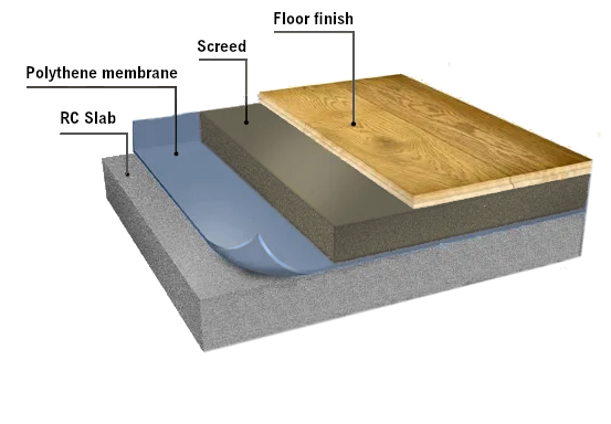
'<p><b>Self weight</b></p>
'ㅤPlate -'g_pl = h_pl*a*γ_c
'ㅤBeam -'g_b = b_b*(h_b - h_pl)*γ_c
'ㅤTotal for beam -'sw = g_pl + g_b
'ㅤColumn -'g_c = b_c*h_c*γ_c
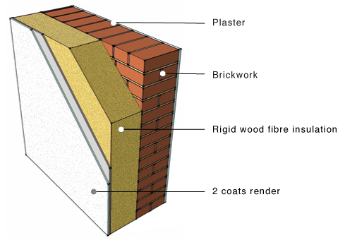
'<p><b>Dead loads</b></p>
'ㅤScreed -'g_scr = 8cm*a*γ_scr
'ㅤFinishes -'g_fin = 2cm*a*γ_fin
'ㅤPlaster ceiling -'g_pls = 2cm*a*γ_pla
'ㅤBrick wall -'g_bw = 25cm*(h_st - h_b)*γ_bw
'ㅤWall insulation -'g_ins = 15cm*h_st*γ_ins
'ㅤWall plaster/render -'g_plw = 2*2cm*h_st*γ_pla
'<img style="width:240pt; max-width:50%;" src="./Images/floor_finishes.png" alt="floor_finishes.png"><img style="width:240pt; max-width:50%;" src="./Images/wall_layers.png" alt="wall_layers.png">
'Total dead load
dl = g_scr + g_fin + g_pls + g_bw + g_ins + g_plw
'<p><b>Live load</b> -'ll = a*2kN/m^2'</p>
'<p><b>Total load</b></p>
'On beams -'p_b = (sw + dl)*1.35 + ll*1.5
'On columns -'p_c = g_c*1.35
#hide
q_x = vector_hp(n_E)*kN/m
q_y = vector_hp(n_E)*kN/m
$Repeat{q_y.i = -p_c @ i = 1 : n_CE}
$Repeat{q_y.(n_CE + i) = -p_b @ i = 1 : n_BE}
#show
'Load values on elements
q_x
q_y
'<h4>Scheme of the structure</h4>
#hide
w = n_b*l_b
h = n_st*h_st
W = 100*n_b
k_w = W/w
H = h*k_w + 100*(1 - n_st/20)
#def svg$ = '<svg viewbox="'-1m*k_w' '-2.5m*k_w' '(w + 4m)*k_w' '(h + 5m)*k_w'" xmlns="http://www.w3.org/2000/svg" version="1.1" style="font-family: Georgia Pro; font-size:8px; width:'W + 120'pt; height:'H + 80'pt">
#def thin_style$ = style = "stroke:green; stroke-width:1; fill:none"
#def thick_style$ = style = "stroke:green; stroke-width:2; fill:none"
k_q = 0.4*m/kN
#show
#val
svg$
#for i = 1 : n_E
#hide
x1 = x_1(i)*k_w
y1 = (h - y_1(i))*k_w
x2 = x_2(i)*k_w
y2 = (h - y_2(i))*k_w
q_yi = q_y.i
α = atan2(c(i); s(i))
#if α ≥ 135
α = α - 180
#end if
#if α < -45
α = α + 180
#else if α < 0
α = 360 + α
#end if
#if q_yi ≠ 0kN/m
#hide
x3 = x2','y3 = y2 + q_yi*k_q
x4 = x1','y4 = y1 + q_yi*k_q
#if abs(c(i)) > 0.1
x = (x3 + x4)/2
y = (y3 + y4)/2 + 5*sign(q_yi)
#else
x = (x3 + x4)/2 - 8*sign(q_yi)
y = (y3 + y4)/2
#end if
#show
#if abs(c(i)) > 0.1
'<polygon points="'x1','y1' 'x2','y2' 'x3','y3' 'x4','y4'" style="stroke:dodgerblue; stroke-width:1; stroke-opacity:0.4; fill:dodgerblue; fill-opacity:0.15;" />
#end if
text$(x;y;α;qy='abs(q_yi)')
#end if
#show
line$(x1; y1; x2; y2; main_style$)
#loop
'<g id="frame">
#for i = 1 : n_E
#hide
x1 = x_1(i)*k_w
y1 = (h - y_1(i))*k_w
x2 = x_2(i)*k_w
y2 = (h - y_2(i))*k_w
#show
line$(x1; y1; x2; y2; main_style$)
#loop
#for i = 1 : n_c
#hide
j = c.(i; 1)
x1 = x_J.j*k_w
y1 = (h - y_J.j)*k_w
δ = 10
x2 = x1 - δ
y2 = y1 - abs(δ)
x3 = x1 + δ
y3 = y1 + abs(δ)
#show
#if c.(i; 2) ≠ 0kN/m
#if c.(i; 3) ≠ 0kN/m
#if c.(i; 4) ≠ 0kNm
line$(x1; y1; x1; y3; thin_style$)
line$(x2; y3; x3; y3; thick_style$)
#else
line$(x2; y3; x3; y3; thick_style$)
line$(x2; y3; x1; y1; thin_style$)
line$(x3; y3; x1; y1; thin_style$)
#end if
#else
#if c.(i; 4) ≠ 0kNm
line$(x1; y1; x2; y1; thin_style$)
line$(x2; y2; x2; y3; thick_style$)
line$(x2 - δ/2; y2; x2 - δ/2; y3; thick_style$)
#else
line$(x2; y2; x1; y1; thin_style$)
line$(x2; y3; x1; y1; thin_style$)
line$(x2; y2; x2; y3; thin_style$)
line$(x2 - δ/2; y2; x2 - δ/2; y3; thick_style$)
#end if
#end if
#else
#if c.(i; 3) ≠ 0kN/m
#if c.(i; 4) ≠ 0kNm
line$(x1; y1; x1; y3; thin_style$)
line$(x2; y3; x3; y3; thick_style$)
line$(x2; y3 + abs(δ)/2; x3; y3 + abs(δ)/2; thick_style$)
#else
line$(x2; y3; x3; y3; thin_style$)
line$(x2; y3; x1; y1; thin_style$)
line$(x3; y3; x1; y1; thin_style$)
line$(x2; y3 + abs(δ)/2; x3; y3 + abs(δ)/2; thick_style$)
#end if
#else
line$(x2; y2; x3; y3; thick_style$)
#end if
#end if
#loop
'</g>
#for i = 1 : n_E
#hide
x = (x_1(i) + x_2(i))*k_w/2
y = (h - (y_1(i) + y_2(i))/2)*k_w
#show
#if i ≤ n_CE
textv$(x - 0.15m*k_w; y; e'i')
#else
texth$(x; y - 0.15m*k_w; e'i')
#end if
#loop
#for i = 1 : n_J
texth$((x_J.i + 0.4m)*k_w; (h - y_J.i - 0.2m)*k_w; j'i')
point$(x_J.i*k_w; (h - y_J.i)*k_w; point_style$)
#loop
#for i = 1 : n_st
dimv$((w + 1.2m)*k_w; (h - i*h_st)*k_w; (h - (i-1)*h_st)*k_w; 'h_st')
#loop
dimv$((w + 2m)*k_w; 0; h*k_w; 'h - y_J.4')
#for i = 1 : n_b
dimh$((i-1)*l_b*k_w; i*l_b*k_w; (h + 0.8m)*k_w; 'l_b')
#loop
dimh$(0; w*k_w; (h + 1.6m)*k_w; 'w')
'</svg>
#equ
'<h4>Materials</h4>
'Modules of elasticity -'E = hp([35GPa])
'Poisson coefficients -'ν = hp([0.2])
'Shear modules -'G = E/(2*(1 + ν))
'Assignments on elements
e_M = fill(vector_hp(n_E); 1)
'<h4>Cross sections</h4>
'Calculation of effective flange width
l_0 = 0.85*l_b
b_eff = b_b + min(0.2*a + 0.1*l_0; 0.2*l_0)
#hide
b = vector_hp(2)*mm','h = vector_hp(2)*mm','b_f = vector_hp(2)*mm','h_f = vector_hp(2)*mm
#show
'Section 1 -'b.1 = b_c','h.1 = h_c'- columns
'Section 2 -'b.2 = b_b','h.2 = h_b' - beams
'ㅤㅤㅤㅤ ' _
b_f.2 = b_eff','h_f.2 = h_pl
'<h4>Cross section properties</h4>
'Area
'ㅤWeb -'A_w = b*h|cm^2
'ㅤFlange -'A_f = (b_f - b)*h_f|cm^2
'ㅤTotal -'A = A_w + A_f|cm^2
'First moment of area -'S = A_w*h/2 + A_f*(h - h_f/2)|cm^3
'Geometrical center -'z_c = S/A|mm
'Second moment of area
'ㅤWeb -'I_w = A_w*(h^2/12 + (z_c - h/2)^2)|cm^4
'ㅤFlange -'I_f = A_f*(h_f^2/12 + (h - z_c - h_f/2)^2)|cm^4
'ㅤTotal -'I = I_w + I_f|cm^4
'Shear area -'A_s = A/1.2
'Assignment on elements
'ㅤColumns -'e_SC = fill(vector_hp(n_CE); 1)
'ㅤBeams -'e_SB = fill(vector_hp(n_BE); 2)
'ㅤAll-'e_S = hp([e_SC; e_SB])
'<h4>Element stiffness matrix</h4>
'Elastic properties for element "e"
EA_e(e) = E.e_M.e*A.e_S.e', 'EI_e(e) = E.e_M.e*I.e_S.e', ' _
GA_s(e) = G.e_M.e*A_s.e_S.e
k_s(e) = 12*EI_e(e)/(GA_s(e)*l(e)^2)', ' _
α(e) = EA_e(e)/l(e)','β(e) = EI_e(e)/(l(e)^3*(1 + k_s(e)))
'Stiffness matrix coefficients for element "e"
k_11(e) = α(e)*(m/kN)','k_22(e) = 12*β(e)*(m/kN)','k_23(e) = 6*β(e)*l(e)*(1/kN)
k_33(e) = (4 + k_s(e))*β(e)*l(e)^2*(1/kNm)',' _
k_36(e) = (2 - k_s(e))*β(e)*l(e)^2*(1/kNm)
'Assembling the 3x3 stiffness matrix blocks for element "e"
k_ii(e) = hp([k_11(e)|0; k_22(e); k_23(e)|0; k_23(e); k_33(e)])
k_ij(e) = hp([-k_11(e)|0; -k_22(e); k_23(e)|0; -k_23(e); k_36(e)])
k_ji(e) = transp(k_ij(e))
k_jj(e) = hp([k_11(e)|0; k_22(e); -k_23(e)|0; -k_23(e); k_33(e)])
'Full element stiffness matrix
k_E(e) = stack(augment(k_ii(e); k_ij(e)); augment(k_ji(e); k_jj(e)))
'Stiffness matrices obtained in local coordinates
k_E(1)
n_b1 = n_CE + 1
k_E(n_b1)
'Stiffness matrices obtained in global coordinates
transp(T(1))*k_E(1)*T(1)
transp(T(n_b1))*k_E(n_b1)*T(n_b1)
'<h4>Global stiffness matrix</h4>
#hide
K = symmetric_hp(3*n_J)
'Add element stiffness matrices
#for e = 1 : n_E
i = 3*e_J.(e; 1) - 2','j = 3*e_J.(e; 2) - 2
t = t(e)','tT = transp(t)
add(tT*k_ii(e)*t; K; i; i)
#if j > i
add(tT*k_ij(e)*t; K; i; j)
#else
add(tT*k_ji(e)*t; K; j; i)
#end if
add(tT*k_jj(e)*t; K; j; j)
#loop
'Add supports
#for i = 1 : n_c
j = 3*c.(i; 1) - 2
add(vec2diag(last(row(c; i); 3)/[kN/m; kN/m; kNm]); K; j; j)
#loop
#show
K
'<h4>Element load vector</h4>
'Lateral load in local CS -'q_E(e) = -q_x.e*s(e) + q_y.e*c(e)
'Axial load in local CS -'n_E(e) = q_x.e*c(e) + q_y.e*s(e)
'Equivalent loads at element endpoints
F_Ex(e) = q_x.e*l(e)/2*(1/kN)','F_Ey(e) = q_y.e*l(e)/2*(1/kN)' ,' _
M_E(e) = q_E(e)*l(e)^2/12*(1/kNm)
'Load vector -'F_E(e) = hp([F_Ex(e); F_Ey(e); M_E(e); F_Ex(e); F_Ey(e); -M_E(e)])
'<h4>Global load vector</h4>
#hide
F = vector_hp(3*n_J)
#for e = 1 : n_E
#for jj = 1 : 2
j = 3*e_J.(e; jj) - 3
F.(j + 1) = F.(j + 1) + take(3*jj - 2; F_E(e))
F.(j + 2) = F.(j + 2) + take(3*jj - 1; F_E(e))
F.(j + 3) = F.(j + 3) + take(3*jj; F_E(e))
#loop
#loop
Tol = 10^-2
#show
F
'<h4>Results</h4>
'<p><b>Solution of the system of equations by PCG method</b></p>
#if n_st*n_b < 20
Z = clsolve(K; F)
#else
Z = slsolve(K; F)
#end if
'<p><b>Joint displacements</b></p>
z_J(j) = slice(Z; 3*j - 2; 3*j)
z(j) = round(z_J(j)/δz)*δz*1000*[mm; mm; 1]
'<p><b>Support reactions</b></p>
r(i) = row(c; i)','j(i) = take(1; r(i))
R(i) = -z_J(j(i))*[m; m; 1]*last(r(i); 3)
#novar
#for i = 1 : n_c
#val
'<p>Joint <b>J'j(i)' -
#equ
'</b>'R(i)'</p>
#loop
#varsub
'<p><b>Element end forces</b></p>
z_E(e) = hp([z_J(e_J.(e; 1)); z_J(e_J.(e; 2))])
R_E(e) = col(k_E(e)*T(e)*z_E(e) - T(e)*F_E(e); 1)*[1; 1; m; 1; 1; m]*kN
'<p><b>Element internal forces</b></p>
N(e; x) = -take(1; R_E(e)) - n_E(e)*x', ' _
Q(e; x) = take(2; R_E(e)) + q_E(e)*x
M(e; x) = -take(3; R_E(e)) + take(2; R_E(e))*x + q_E(e)*x^2/2
#hide
R(e; x; i) = take(i; N(e; x); Q(e; x); M(e; x))
w = n_b*l_b
h = n_st*h_st
k_w = W/w
#def red_style$ = style = "stroke:salmon; stroke-width:1; fill:none"
#deg
#for i = 1 : 3
#hide
sgn = take(i; 1; 1; -1)
unit = take(i; kN; kN; kNm)
tol = 0.01*unit
R = vector_hp(n_E)*unit
$Repeat{R.e = $Sup{R(e; x; i) @ x = 0m : l(e)} @ e = 1 : n_E}
R_max = max(R)
$Repeat{R.e = abs($Inf{R(e; x; i) @ x = 0m : l(e)}) @ e = 1 : n_E}
R_max = max(max(R); R_max)
k_R = sgn*0.8m*k_w/R_max
#show
#if i ≡ 1
'<p><b>Axial forces diagram, kN</b></p>
#else if i ≡ 2
'<p><b>Shear forces diagram, kN</b></p>
#else
'<p><b>Bending moments diagram, kNm</b></p>
#end if
#val
svg$
#for e = 1 : n_E
#hide
x1 = x_1(e)*k_w
y1 = (h - y_1(e))*k_w
x2 = x_2(e)*k_w
y2 = (h - y_2(e))*k_w
c_e = c(e)
s_e = s(e)
l_e = l(e)
st = l_e/10
xd2 = x1
yd2 = y1
#show
#for j = 0 : 10
#hide
xd1 = xd2
yd1 = yd2
x = j*st*k_w
val = R(e; j*st; i)
y = val*k_R
xd2 = x1 + x*c_e - y*s_e
yd2 = y1 - x*s_e - y*c_e
α = 90 + atan2(c_e; s_e)
#if α ≥ 135
α = α - 180
#end if
#if α < -45
α = α + 180
#else if α < 0
α = 360 + α
#end if
d = -(10 + 5*(i ≡ 1))*sign(val*sgn)
#if j ≡ 0
xt = xd2 + d*s_e + 0.4m*k_w*c_e
yt = yd2 + d*c_e - 0.2m*k_w*s_e
#else if j ≡ 5
xt = xd2 + (d + 2)*s_e + 0.1m*k_w*c_e
yt = yd2 + (d + 2)*c_e + 0.2m*k_w*s_e
#else if j ≡ 10
xt = xd2 + d*s_e - 0.2m*k_w*c_e
yt = yd2 + d*c_e + 0.4m*k_w*s_e
#end if
#show
line$(xd1; yd1; xd2; yd2; red_style$)
#if abs(val) > tol
#if j ≡ 0 ∨ j ≡ 10
text$(xt; yt; α; 'val')
#else if i ≡ 3 ∧ j ≡ 5 ∧ e > n_CE
text$(xt; yt; α; 'val')
#end if
line$(xd1; yd1; xd2; yd2; red_style$)
#end if
#loop
#hide
xd1 = x2
yd1 = y2
#show
line$(xd1; yd1; xd2; yd2; red_style$)
#loop
'<use href="#frame"/>
'</svg>
#loop
#equ
'<p><b>Deformed shape</b></p>
'Shape function in relative coordinates ξ = x/l (with account to shear deflections)
Φ_1(e; ξ) = 1/(1 + k_s(e))*(1 + k_s(e) - k_s(e)*ξ - 3*ξ^2 + 2*ξ^3)
Φ_2(e; ξ) = ξ*l(e)*m^-1/(1 + k_s(e))*(1 + k_s(e)/2 - (2 + k_s(e)/2)*ξ + ξ^2)
Φ_3(e; ξ) = ξ/(1 + k_s(e))*(k_s(e) + 3*ξ - 2*ξ^2)
Φ_4(e; ξ) = ξ*l(e)*m^-1/(1 + k_s(e))*(-k_s(e)/2 - (1 - k_s(e)/2)*ξ + ξ^2)
'Element endpoint displacements and rotations
z_E,loc(e) = T(e)*z_E(e)
u_1(e) = take(1; z_E,loc(e))','v_1(e) = take(2; z_E,loc(e))','φ_1(e) = take(3; z_E,loc(e))
u_2(e) = take(4; z_E,loc(e))','v_2(e) = take(5; z_E,loc(e))','φ_2(e) = take(6; z_E,loc(e))
'Displacement functions (with account for intermediate loads)
u(e; ξ) = u_1(e)*(1 - ξ) + u_2(e)*ξ + n_E(e)*.m/EA_e(e)*ξ*(1 - ξ)
v(e; ξ) = v_1(e)*Φ_1(e; ξ) + φ_1(e)*Φ_2(e; ξ) + v_2(e)*Φ_3(e; ξ) + φ_2(e)*Φ_4(e; ξ) + q_E(e)*l(e)^4/(24*EI_e(e))*(ξ^2*(1 - ξ)^2/.m) + q_E(e)*l(e)^2/(2*GA_s(e))*(ξ*(1 - ξ)/.m)
'Deformed shape, mm
#val
#hide
tol = 0.00001
k_R = 10/max(abs(Z))
#show
svg$
'<use href="#frame" style="opacity:0.4;"/>
#for e = 1 : n_E
#hide
x1 = x_1(e)*k_w
y1 = (h - y_1(e))*k_w
x2 = x_2(e)*k_w
y2 = (h - y_2(e))*k_w
c_e = c(e)
s_e = s(e)
l_e = l(e)
u_x = u(e; 0)
v_y = v(e; 0)
x = u_x*k_R
y = v_y*k_R
xd2 = x1 + x*c_e - y*s_e
yd2 = y1 - x*s_e - y*c_e
#show
#for j = 0 : 10
#hide
xd1 = xd2
yd1 = yd2
ξ = j/10
u_x = u(e; ξ)
v_y = v(e; ξ)
x = ξ*l_e*k_w + u_x*k_R
y = v_y*k_R
xd2 = x1 + x*c_e - y*s_e
yd2 = y1 - x*s_e - y*c_e
d = -15*sign(v_y)
#show
line$(xd1; yd1; xd2; yd2; red_style$)
#loop
#loop
#for j = 1 : n_J
#hide
z_J = z_J(j)
u_x = z_J.1
v_y = z_J.2
x = x_J.j*k_w + u_x*k_R
y = (h - y_J.j)*k_w - v_y*k_R
dx = 0.5m*k_w*sign(u_x)
dy = -0.5m*k_w*sign(v_y)
#show
#if abs(u_x) > tol
texth$(x - dx; y - 0.2*abs(dy); 'u_x*1000')
#end if
#if abs(v_y) > tol
textv$(x - 0.2*abs(dx); y + dy; 'v_y*1000')
#end if
#loop
'</svg>
Number of stories - nst = 5 , Number of bays - nb = 3
Story height - hst = 2.85 m ,ㅤBay length - lb = 4 m
Slab thickness - hpl = 18 cm
Cross section of columns - bc = 25 cm , hc = 60 cm
Cross section of beams -ㅤ bb = 25 cm , hb = 40 cm
⃗xJ = [0 4 8 12 0 4 8 12 0 4 8 12 0 4 8 12 0 4 8 12 ... 12] m
⃗yJ = [0 0 0 0 2.85 2.85 2.85 2.85 5.7 5.7 5.7 5.7 8.55 8.55 8.55 8.55 11.4 11.4 11.4 11.4 ... 14.25] m
transp ( eJ ) = 1234567891011121314151617181920⋯23 56789101112131415161718192021222324⋯24
Element endpoint coordinates
x1 ( e ) = ⃗xJ.eJ.e,1 , y1 ( e ) = ⃗yJ.eJ.e,1 , x2 ( e ) = ⃗xJ.eJ.e,2 , y2 ( e ) = ⃗yJ.eJ.e,2
Element length - l ( e ) = √ ( x2 ( e ) − x1 ( e ) ) 2 + ( y2 ( e ) − y1 ( e ) ) 2
Element direction
c ( e ) = x2 ( e ) − x1 ( e ) l ( e ) , s ( e ) = y2 ( e ) − y1 ( e ) l ( e )
Transformation matrix
Diagonal 3x3 block - t ( e ) = hp ( [c ( e ) ; s ( e ) ; 0 | -s ( e ) ; c ( e ) ; 0 | 0; 0; 1] )
Generation of the full transformation matrix
T ( e ) = add ( t ( e ) ; add ( t ( e ) ; matrix ( 6; 6 ) ; 1; 1 ) ; 4; 4 )
c = 11020 kN ∕ m1020 kN ∕ m0 kNm 21020 kN ∕ m1020 kN ∕ m0 kNm 31020 kN ∕ m1020 kN ∕ m0 kNm 41020 kN ∕ m1020 kN ∕ m0 kNm
ㅤ - concrete - γc = 25 kN ∕ m3
ㅤ - screed - γscr = 21 kN ∕ m3
ㅤ - finishes - γfin = 18 kN ∕ m3
ㅤ - brickwork - γbw = 16 kN ∕ m3
ㅤ - plaster/render - γpla = 16 kN ∕ m3
ㅤ - insulation - γins = 0.5 kN ∕ m3
Total halfwidth of adjacent plate spans - a = 5 m2 = 2.5 m
Self weight
ㅤPlate - gpl = hpl · a · γc = 18 cm · 2.5 m · 25 kN ∕ m3 = 11.25 kN ∕ m
ㅤBeam - gb = bb · ( hb − hpl ) · γc = 25 cm · ( 40 cm − 18 cm ) · 25 kN ∕ m3 = 1.38 kN ∕ m
ㅤTotal for beam - sw = gpl + gb = 11.25 kN ∕ m + 1.38 kN ∕ m = 12.62 kN ∕ m
ㅤColumn - gc = bc · hc · γc = 25 cm · 60 cm · 25 kN ∕ m3 = 3.75 kN ∕ m
Dead loads
ㅤScreed - gscr = 8 cm · a · γscr = 8 cm · 2.5 m · 21 kN ∕ m3 = 4.2 kN ∕ m
ㅤFinishes - gfin = 2 cm · a · γfin = 2 cm · 2.5 m · 18 kN ∕ m3 = 0.9 kN ∕ m
ㅤPlaster ceiling - gpls = 2 cm · a · γpla = 2 cm · 2.5 m · 16 kN ∕ m3 = 0.8 kN ∕ m
ㅤBrick wall - gbw = 25 cm · ( hst − hb ) · γbw = 25 cm · ( 2.85 m − 40 cm ) · 16 kN ∕ m3 = 9.8 kN ∕ m
ㅤWall insulation - gins = 15 cm · hst · γins = 15 cm · 2.85 m · 0.5 kN ∕ m3 = 0.214 kN ∕ m
ㅤWall plaster/render - gplw = 2 · 2 cm · hst · γpla = 2 · 2 cm · 2.85 m · 16 kN ∕ m3 = 1.82 kN ∕ m
Total dead load
dl = gscr + gfin + gpls + gbw + gins + gplw = 4.2 kN ∕ m + 0.9 kN ∕ m + 0.8 kN ∕ m + 9.8 kN ∕ m + 0.214 kN ∕ m + 1.82 kN ∕ m = 17.74 kN ∕ m
Live load - ll = a · 2 kNm2 = 2.5 m · 2 kNm2 = 5 kN ∕ m
Total load
On beams - pb = ( sw + dl ) · 1.35 + ll · 1.5 = ( 12.62 kN ∕ m + 17.74 kN ∕ m ) · 1.35 + 5 kN ∕ m · 1.5 = 48.49 kN ∕ m
On columns - pc = gc · 1.35 = 3.75 kN ∕ m · 1.35 = 5.06 kN ∕ m
Load values on elements
⃗qx = [0 0 0 0 0 0 0 0 0 0 0 0 0 0 0 0 0 0 0 0 ... 0] kN ∕ m
⃗qy = [-5.06 -5.06 -5.06 -5.06 -5.06 -5.06 -5.06 -5.06 -5.06 -5.06 -5.06 -5.06 -5.06 -5.06 -5.06 -5.06 -5.06 -5.06 -5.06 -5.06 ... -48.49] kN ∕ m
Modules of elasticity - ⃗E = hp ( [35 GPa] ) = [35] GPa
Poisson coefficients - ⃗ν = hp ( [0.2] ) = [0.2]
Shear modules - ⃗G = ⃗E2 · ( 1 + ⃗ν ) = [14.58] GPa
Assignments on elements
⃗eM = fill ( vectorhp ( nE ) ; 1 ) = fill ( vectorhp ( 35 ) ; 1 ) = [1 1 1 1 1 1 1 1 1 1 1 1 1 1 1 1 1 1 1 1 ... 1]
Calculation of effective flange width
l0 = 0.85 · lb = 0.85 · 4 m = 3.4 m
beff = bb + min ( 0.2 · a + 0.1 · l0; 0.2 · l0 ) = 25 cm + min ( 0.2 · 2.5 m + 0.1 · 3.4 m; 0.2 · 3.4 m ) = 93 cm
Section 1 - ⃗b1 = bc = 25 cm , ⃗h1 = hc = 60 cm - columns
Section 2 - ⃗b2 = bb = 25 cm , ⃗h2 = hb = 40 cm - beams
ㅤㅤㅤㅤ ⃗bf.2 = beff = 93 cm , ⃗hf.2 = hpl = 18 cm
Area
ㅤWeb - ⃗Aw = ⃗b⊙⃗h = [1500 1000] cm2
ㅤFlange - ⃗Af = ( ⃗bf − ⃗b ) ⊙⃗hf = [0 1224] cm2
ㅤTotal - ⃗A = ⃗Aw + ⃗Af = [1500 2224] cm2
First moment of area - ⃗S = ⃗Aw⊙⃗h2 + ⃗Af⊙(⃗h − ⃗hf2) = [45000 57944] cm3
Geometrical center - ⃗zc = ⃗S⃗A = [300 260.54] mm
Second moment of area
ㅤWeb - ⃗Iw = ⃗Aw⊙(⃗h⊙ 212 + (⃗zc − ⃗h2)⊙ 2) = [450000 169984] cm4
ㅤFlange - ⃗If = ⃗Af⊙(⃗hf⊙ 212 + (⃗h − ⃗zc − ⃗hf2)⊙ 2) = [0 62991.1] cm4
ㅤTotal - ⃗I = ⃗Iw + ⃗If = [450000 232975] cm4
Shear area - ⃗As = ⃗A1.2 = [1250 1853.33] cm2
Assignment on elements
ㅤColumns - ⃗eSC = fill ( vectorhp ( nCE ) ; 1 ) = fill ( vectorhp ( 20 ) ; 1 ) = [1 1 1 1 1 1 1 1 1 1 1 1 1 1 1 1 1 1 1 1]
ㅤBeams - ⃗eSB = fill ( vectorhp ( nBE ) ; 2 ) = fill ( vectorhp ( 15 ) ; 2 ) = [2 2 2 2 2 2 2 2 2 2 2 2 2 2 2]
ㅤAll- ⃗eS = hp ( [⃗eSC; ⃗eSB] ) = [1 1 1 1 1 1 1 1 1 1 1 1 1 1 1 1 1 1 1 1 ... 2]
Elastic properties for element "e"
EAe ( e ) = ⃗E⃗eM.e · ⃗AeS.e , EIe ( e ) = ⃗E⃗eM.e · ⃗IeS.e , GAs ( e ) = ⃗G⃗eM.e · ⃗As.eS.e
ks ( e ) = 12 · EIe ( e ) GAs ( e ) · l ( e ) 2 , α ( e ) = EAe ( e ) l ( e ) , β ( e ) = EIe ( e ) l ( e ) 3 · ( 1 + ks ( e ) )
Stiffness matrix coefficients for element "e"
k11 ( e ) = α ( e ) · mkN , k22 ( e ) = 12 · β ( e ) · mkN , k23 ( e ) = 6 · β ( e ) · l ( e ) · 1kN
k33 ( e ) = ( 4 + ks ( e ) ) · β ( e ) · l ( e ) 2 · 1kNm , k36 ( e ) = ( 2 − ks ( e ) ) · β ( e ) · l ( e ) 2 · 1kNm
Assembling the 3x3 stiffness matrix blocks for element "e"
kii ( e ) = hp ( [k11 ( e ) | 0; k22 ( e ) ; k23 ( e ) | 0; k23 ( e ) ; k33 ( e ) ] )
kij ( e ) = hp ( [-k11 ( e ) | 0; -k22 ( e ) ; k23 ( e ) | 0; -k23 ( e ) ; k36 ( e ) ] )
kji ( e ) = transp ( kij ( e ) )
kjj ( e ) = hp ( [k11 ( e ) | 0; k22 ( e ) ; -k23 ( e ) | 0; -k23 ( e ) ; k33 ( e ) ] )
Full element stiffness matrix
kE ( e ) = stack ( augment ( kii ( e ) ; kij ( e ) ) ; augment ( kji ( e ) ; kjj ( e ) ) )
Stiffness matrices obtained in local coordinates
kE ( 1 ) = 184210500-184210500 072402.71031740-72402.7103174 01031742022860-10317491759.5 -184210500184210500 0-72402.7-103174072402.7-103174 010317491759.50-103174202286
nb1 = nCE + 1 = 20 + 1 = 21
kE ( nb1 ) = kE ( 21 ) = 194600000-194600000 014950.729901.40-14950.729901.4 029901.4801880-29901.439417.4 -194600000194600000 0-14950.7-29901.4014950.7-29901.4 029901.439417.40-29901.480188
Stiffness matrices obtained in global coordinates
transp ( T ( 1 ) ) · kE ( 1 ) · T ( 1 ) = 72402.70-103174-72402.70-103174 0184210500-18421050 -1031740202286103174091759.5 -72402.7010317472402.70103174 0-18421050018421050 -103174091759.51031740202286
transp ( T ( nb1 ) ) · kE ( nb1 ) · T ( nb1 ) = transp ( T ( 21 ) ) · kE ( 21 ) · T ( 21 ) = 194600000-194600000 014950.729901.40-14950.729901.4 029901.4801880-29901.439417.4 -194600000194600000 0-14950.7-29901.4014950.7-29901.4 029901.439417.40-29901.480188
K = 10200-103174000000000-72402.70-10317400000⋯0 0102000000000000-1842105000000⋯0 -1031740202286000000000103174091759.500000⋯0 00010200-103174000000000-72402.70-10317400⋯0 0000102000000000000-1842105000⋯0 000-1031740202286000000000103174091759.500⋯0 00000010200-103174000000000-72402.70⋯0 0000000102000000000000-1842105⋯0 000000-10317402022860000000001031740⋯0 00000000010200-10317400000000⋯0 00000000001020000000000⋯0 000000000-103174020228600000000⋯0 -72402.70103174000000000209080500-19460000000⋯0 0-184210500000000000369916129901.40-14950.729901.400⋯0 -103174091759.5000000000029901.44847600-29901.439417.400⋯0 000-72402.70103174000000-194600000403680500-19460000⋯0 0000-184210500000000-14950.7-29901.40371411200-14950.7⋯0 000-103174091759.5000000029901.439417.4005649480-29901.4⋯0 000000-72402.70103174000000-19460000040368050⋯0 0000000-184210500000000-14950.7-29901.403714112⋯0 ⋮⋮⋮⋮⋮⋮⋮⋮⋮⋮⋮⋮⋮⋮⋮⋮⋮⋮⋮⋮⋱⋮00000000000000000000⋯282474
Lateral load in local CS - qE ( e ) = -⃗qx.e · s ( e ) + ⃗qy.e · c ( e )
Axial load in local CS - nE ( e ) = ⃗qx.e · c ( e ) + ⃗qy.e · s ( e )
Equivalent loads at element endpoints
FEx ( e ) = ⃗qx.e · l ( e ) 2 · 1kN , FEy ( e ) = ⃗qy.e · l ( e ) 2 · 1kN , ME ( e ) = qE ( e ) · l ( e ) 212 · 1kNm
Load vector - FE ( e ) = hp ( [FEx ( e ) ; FEy ( e ) ; ME ( e ) ; FEx ( e ) ; FEy ( e ) ; -ME ( e ) ] )
⃗F = [0 -7.21 0 0 -7.21 0 0 -7.21 0 0 -7.21 0 0 -111.41 -64.65 0 -208.39 0 0 -208.39 ... 64.65]
Solution of the system of equations by PCG method
⃗Z = clsolve ( K; ⃗F ) = [0 -5.72×10⁻¹⁸ 7.06×10⁻⁵ 0 -1.03×10⁻¹⁷ 3.03×10⁻⁶ 0 -1.03×10⁻¹⁷ -3.03×10⁻⁶ 0 -5.72×10⁻¹⁸ -7.06×10⁻⁵ -1.33×10⁻⁵ -0.000306 -0.000141 -4.64×10⁻⁶ -0.000554 -1.45×10⁻⁶ 4.64×10⁻⁶ -0.000554 ... 0.000283]
Joint displacements
zJ ( j ) = slice ( ⃗Z; 3 · j − 2; 3 · j )
z ( j ) = round(zJ ( j ) δz) · δz · 1000 · [mm; mm; 1]
Support reactions
r ( i ) = row ( c; i ) , j ( i ) = take ( 1; r ( i ) ) !!!
R ( i ) = -zJ ( j ( i ) ) · [m; m; 1] · last ( r ( i ) ; 3 )
Joint J1 - R ( 1 ) = [8.2 kN 571.78 kN 0 kNm]
Joint J2 - R ( 2 ) = [0.174 kN 1027.2 kN 0 kNm]
Joint J3 - R ( 3 ) = [-0.174 kN 1027.2 kN 0 kNm]
Joint J4 - R ( 4 ) = [-8.2 kN 571.78 kN 0 kNm]
Element end forces
zE ( e ) = hp ( [zJ ( eJ.e,1 ) ; zJ ( eJ.e,2 ) ] )
RE ( e ) = col ( kE ( e ) · T ( e ) · zE ( e ) − T ( e ) · FE ( e ) ; 1 ) · [1; 1; m; 1; 1; m] · kN
Element internal forces
N ( e; x ) = -take ( 1; RE ( e ) ) − nE ( e ) · x , Q ( e; x ) = take ( 2; RE ( e ) ) + qE ( e ) · x
M ( e; x ) = -take ( 3; RE ( e ) ) + take ( 2; RE ( e ) ) · x + qE ( e ) · x22
Axial forces diagram, kN
Shear forces diagram, kN
Bending moments diagram, kNm
Deformed shape
Shape function in relative coordinates ξ = x/l (with account to shear deflections)
Φ1 ( e; ξ ) = 11 + ks ( e ) · ( 1 + ks ( e ) − ks ( e ) · ξ − 3 · ξ2 + 2 · ξ3 )
Φ2 ( e; ξ ) = ξ · l ( e ) · m-11 + ks ( e ) · (1 + ks ( e ) 2 − (2 + ks ( e ) 2) · ξ + ξ2)
Φ3 ( e; ξ ) = ξ1 + ks ( e ) · ( ks ( e ) + 3 · ξ − 2 · ξ2 )
Φ4 ( e; ξ ) = ξ · l ( e ) · m-11 + ks ( e ) · (-ks ( e ) 2 − (1 − ks ( e ) 2) · ξ + ξ2)
Element endpoint displacements and rotations
zE,loc ( e ) = T ( e ) · zE ( e )
u1 ( e ) = take ( 1; zE,loc ( e ) ) , v1 ( e ) = take ( 2; zE,loc ( e ) ) , φ1 ( e ) = take ( 3; zE,loc ( e ) )
u2 ( e ) = take ( 4; zE,loc ( e ) ) , v2 ( e ) = take ( 5; zE,loc ( e ) ) , φ2 ( e ) = take ( 6; zE,loc ( e ) )
Displacement functions (with account for intermediate loads)
u ( e; ξ ) = u1 ( e ) · ( 1 − ξ ) + u2 ( e ) · ξ + nE ( e ) · mEAe ( e ) · ξ · ( 1 − ξ )
v ( e; ξ ) = v1 ( e ) · Φ1 ( e; ξ ) + φ1 ( e ) · Φ2 ( e; ξ ) + v2 ( e ) · Φ3 ( e; ξ ) + φ2 ( e ) · Φ4 ( e; ξ ) + qE ( e ) · l ( e ) 424 · EIe ( e ) · ξ2 · ( 1 − ξ ) 2m + qE ( e ) · l ( e ) 22 · GAs ( e ) · ξ · ( 1 − ξ ) m
Deformed shape, mm
Spotted an error? Edit these examples.