Simply Supported Beams
CalcpadCE worksheets in this section collect the standard load cases for the simply supported beam — a span resting on a pin at one end and a roller at the other. The system is statically determinate, so the reactions and internal forces follow from equilibrium alone and depend only on the geometry and the applied load.
A single point force and a point moment at distance \(a\) from the left support cover the basic concentrated cases, while a series of equal concentrated forces at constant spacing \(a = l / (n + 1)\) models a row of identical loads such as wheel groups or hangers. For distributed actions, the uniform load reproduces the classroom \(M_{max} = q l^2 / 8\), \(V_{max} = q l / 2\) result, the linearly varying load covers the trapezoidal and triangular shapes via end intensities \(q_1\) and \(q_2\), and the partial uniform load acts on a stretch of length \(b\) between offsets \(a\) and \(c = l - a - b\).
Span, load magnitudes, distances and a probe coordinate \(x_1\) are exposed as inputs, so \(M(x_1)\) and \(V(x_1)\) can be picked off the bending and shear diagrams at any cross-section.
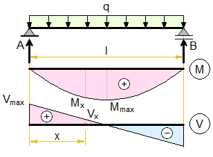
Uniformly Distributed Load
Full-span uniform load \(q\), recovering the textbook results \(M_{max} = q l^2 / 8\) and \(V_{max} = q l / 2\).
'<div style = "max-width:180mm;">
'<img style="width:190pt;" alt = simply-supported-beam-distributed-load-uniform.png" class="side" src = "../../Images/mechanics/beams/simply-supported-beam-distributed-load-uniform.png">
'<p><b>Input data</b></p>
'Beam length -'l = ?'m
'Load -'q = ?'kN/m
#post
'<p><b>Internal forces</b></p>
'Bending -'M_max = q*l^2/8'kN·m
'Shear -'V_max = q*l/2'kN
'<p><b>Diagrams</b></p>
#hide
PlotWidth = 600
PlotHeight = 150
#show
'Calculate internal forces at'x_1 = ?'m
#pre
#post
'Bending
M(x) = q*x*(l - x)/2
$Plot{-M(x) @ x = 0 : l}
M(x_1)'kN·m
'Shear
V(x) = q*(l/2 - x)
$Plot{V(x) @ x = 0 : l}
V(x_1)'kN
#show
'</div>
5 10 1
Input data
Beam length - l = 5 m
Load - q = 10 kN/m
Internal forces
Bending - Mmax = q · l28 = 10 · 528 = 31.25 kN·m
Shear - Vmax = q · l2 = 10 · 52 = 25 kN
Diagrams
Calculate internal forces at x1 = 1 m
Bending
M ( x ) = q · x · ( l − x ) 2

M ( x1 ) = M ( 1 ) = 20 kN·m
Shear
V ( x ) = q · (l2 − x)

V ( x1 ) = V ( 1 ) = 15 kN
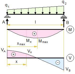
Linearly Distributed Load
Trapezoidal load defined by end intensities \(q_1\) and \(q_2\), locating the in-span peak from the zero of \(V(x)\) and falling back to the uniform and triangular special cases.
'<div style = "max-width:180mm;">
'<img style="width:190pt;" alt = "simply-supported-beam-distributed-load-linear.png" class="side" src = "../../Images/mechanics/beams/simply-supported-beam-distributed-load-linear.png">
'<p><b>Input data</b></p>
'Beam length -'l = ?'m
'Load -'q_1 = ?'kN/m,'q_2 = ?'kN/m
#post
Δq = q_2 - q_1'kN/m
'<p><b>Internal forces</b></p>
#if '<!--'q_1 ≡ q_2'-->
'Bending -'M_max = q_1*l^2/8
#else if '<!--'q_1 ≡ 0'-->
'Distance -'x_max = l/sqr(3)'m
'Bending
M_max = Δq*l^2/(9*sqr(3))'kN·m
#else
k = Δq/q_1
'Distance
x_max = l/k*(sqr(1 + k + k^2/3) - 1)'m
'Bending
M_max = q_1*x_max*(l - x_max)/2 + Δq*x_max*l*(1 - (x_max/l)^2)/6'kN·m
#end if
'Shear
V_A = l*(q_1/2 + Δq/6)'kN
V_B = l*(q_1/2 + Δq/3)'kN
'<p><b>Diagrams</b></p>
#hide
PlotWidth = 600
PlotHeight = 150
#show
'Calculate internal forces at'x_1 = ?'m
#pre
#post
'Bending
M(x) = q_1*x*(l - x)/2 + Δq*x*l*(1 - (x/l)^2)/6
$Plot{-M(x) @ x = 0 : l}
M(x_1)'kN·m
'Shear
V(x) = q_1*(l/2 - x) + Δq*(l/6 - x^2/(2*l))
$Plot{V(x) @ x = 0 : l}
V(x_1)'kN
#show
'</div>
5 5 15 1
Input data
Beam length - l = 5 m
Load - q1 = 5 kN/m, q2 = 15 kN/m
Δq = q2 − q1 = 15 − 5 = 10 kN/m
Internal forces
k = Δqq1 = 105 = 2
Distance
xmax = lk · ( 1 + k + k23 − 1) = 52 · ( 1 + 2 + 223 − 1) = 2.7 m
Bending
Mmax = q1 · xmax · ( l − xmax ) 2 + Δq · xmax · l · (1 − (xmaxl)2)6 = 5 · 2.7 · ( 5 − 2.7 ) 2 + 10 · 2.7 · 5 · (1 − (2.75)2)6 = 31.46 kN·m
Shear
VA = l · (q12 + Δq6) = 5 · (52 + 106) = 20.83 kN
VB = l · (q12 + Δq3) = 5 · (52 + 103) = 29.17 kN
Diagrams
Calculate internal forces at x1 = 1 m
Bending
M ( x ) = q1 · x · ( l − x ) 2 + Δq · x · l · (1 − (xl)2)6

M ( x1 ) = M ( 1 ) = 18 kN·m
Shear
V ( x ) = q1 · (l2 − x) + Δq · (l6 − x22 · l)

V ( x1 ) = V ( 1 ) = 14.83 kN
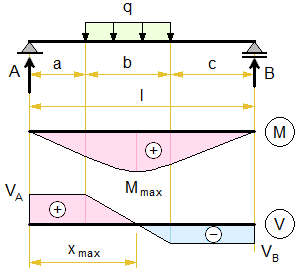
Partially Distributed Load
Uniform load \(q\) acting on a stretch of length \(b\) between offsets \(a\) and \(c = l - a - b\), with a guard against an invalid load length when \(a + b > l\).
'<div style = "max-width:180mm;">
'<img style="width:190pt;" alt = "simply-supported-beam-distributed-load-partial.png" class="side" src = "../../Images/mechanics/beams/simply-supported-beam-distributed-load-partial.png">
'<p><b>Input data</b></p>
'Beam length -'l = ?'m
'Load -'q = ?'kN/m
'Distances -'a = ?'m,'b = ?'m
#post
c = l - (a + b)'m
#if '<!--'c < 0'-->
'<p class="err">Invalid load length</p>
#else
'<p><b>Internal forces</b></p>
'Distance -'x_max = a + b*(b/2 + c)/l'm
'Bending
M_max = q*(x_max^2 - a^2)/2'kN·m
'Shear
V_A = q*b*(b/2 + c)/l'kN
V_B = -q*b*(b/2 + a)/l'kN
'<p><b>Diagrams</b></p>
#hide
PlotWidth = 600
PlotHeight = 150
#show
'Calculate internal forces at'x_1 = ?'m
#pre
#post
'Bending
M(x) = V_A*x - q*(x - a)^2/2*(x > a) + q*(x - a - b)^2/2*(x > a + b)
$Plot{-M(x) @ x = 0 : l}
M(x_1)'kN·m
'Shear
V(x) = V_A - q*(x - a)*(x > a) + q*(x - a - b)*(x > a + b)
$Plot{V(x) @ x = 0 : l}
V(x_1)'kN
#end if
#show
'</div>
5 10 1 2 1.5
Input data
Beam length - l = 5 m
Load - q = 10 kN/m
Distances - a = 1 m, b = 2 m
c = l − ( a + b ) = 5 − ( 1 + 2 ) = 2 m
Internal forces
Distance - xmax = a + b · (b2 + c)l = 1 + 2 · (22 + 2)5 = 2.2 m
Bending
Mmax = q · ( xmax2 − a2 ) 2 = 10 · ( 2.22 − 12 ) 2 = 19.2 kN·m
Shear
VA = q · b · (b2 + c)l = 10 · 2 · (22 + 2)5 = 12 kN
VB = -q · b · (b2 + a)l = -10 · 2 · (22 + 1)5 = -8 kN
Diagrams
Calculate internal forces at x1 = 1.5 m
Bending
M ( x ) = VA · x − q · ( x − a ) 22 · ( x > a ) + q · ( x − a − b ) 22 · ( x > a + b )

M ( x1 ) = M ( 1.5 ) = 16.75 kN·m
Shear
V ( x ) = VA − q · ( x − a ) · ( x > a ) + q · ( x − a − b ) · ( x > a + b )

V ( x1 ) = V ( 1.5 ) = 7 kN
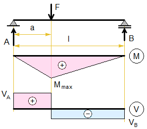
Concentrated Force
Single point force \(F\) at distance \(a\) from the left support, with reactions \(V_A = F (l - a) / l\), \(V_B = -F a / l\) and the bending peak \(M_{max} = F (l - a) a / l\) at the load.
'<div style = "max-width:180mm;">
'<img style="width:190pt;" alt = "simply-supported-beam-concentrated-force.png" class="side" src = "../../Images/mechanics/beams/simply-supported-beam-concentrated-force.png">
'<p><b>Input data</b></p>
'Beam length -'l = ?'m
'Load -'F = ?'kN
'Distance -'a = ?'m
#post
'<p><b>Internal forces</b></p>
'Bending
M_max = F*(l - a)*a/l'kN·m
'Shear
V_A = F*(l - a)/l'kN
V_B = -F*a/l'kN
'<p><b>Diagrams</b></p>
#hide
PlotWidth = 600
PlotHeight = 150
#show
'Calculate internal forces at'x_1 = ?'m
#pre
#post
'Bending
M(x) = V_A*x - F*(x - a)*(x > a)
$Plot{-M(x) @ x = 0 : l}
M(x_1)'kN·m
'Shear
V(x) = V_A - F*(x > a)
$Plot{V(x) @ x = 0 : l}
V(x_1)'kN
#show
'</div>
5 10 2 1
Input data
Beam length - l = 5 m
Load - F = 10 kN
Distance - a = 2 m
Internal forces
Bending
Mmax = F · ( l − a ) · al = 10 · ( 5 − 2 ) · 25 = 12 kN·m
Shear
VA = F · ( l − a ) l = 10 · ( 5 − 2 ) 5 = 6 kN
VB = -F · al = -10 · 25 = -4 kN
Diagrams
Calculate internal forces at x1 = 1 m
Bending
M ( x ) = VA · x − F · ( x − a ) · ( x > a )

M ( x1 ) = M ( 1 ) = 6 kN·m
Shear
V ( x ) = VA − F · ( x > a )

V ( x1 ) = V ( 1 ) = 6 kN
Concentrated Forces
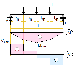
Series of \(n\) equal forces \(F\) spaced at \(a = l / (n + 1)\), with \(M_{max}\) taken at mid-span and switching between the odd-\(n\) and even-\(n\) closed forms.
'<div style = "max-width:180mm;">
'<img style="width:190pt;" alt = "simply-supported-beam-forces.png" class="side" src = "../../Images/mechanics/beams/simply-supported-beam-forces.png">
'<p><b>Input data</b></p>
'Beam length -'l = ?'m
'Load -'F = ?'kN
'Number of forces -'n = ?
#post
'Number of spacings -'n_1 = n + 1
'<p><b>Internal forces</b></p>
#if '<!--'n%%2 ≡ 0'-->
'Bending -'M_max = (n_1^2 - 1)*F*l/(8*n_1)'kN·m
#else
'Bending -'M_max = n_1*F*l/8'kN·m
#end if
'Shear -'V_max = n*F/2'kN
'<p><b>Diagrams</b></p>
#hide
PlotWidth = 600
PlotHeight = 150
#show
'Calculate internal forces at'x_1 = ?'m
#pre
#post
a = l/n_1'm
n(x) = max(ceiling(x/a) - 1; 0)
x_F(x) = n(x)*(x - (n(x) + 1)*a/2)
'Bending
M(x) = V_max*x - F*x_F(x)
$Plot{-M(x) @ x = 0 : l}
M(x_1)'kN·m
'Shear
V(x) = V_max - F*n(x)
$Plot{V(x) @ x = 0 : l}
V(x_1)'kN
#show
'</div>
5 10 2 1
Input data
Beam length - l = 5 m
Load - F = 10 kN
Number of forces - n = 2
Number of spacings - n1 = n + 1 = 2 + 1 = 3
Internal forces
Bending - Mmax = ( n12 − 1 ) · F · l8 · n1 = ( 32 − 1 ) · 10 · 58 · 3 = 16.67 kN·m
Shear - Vmax = n · F2 = 2 · 102 = 10 kN
Diagrams
Calculate internal forces at x1 = 1 m
a = ln1 = 53 = 1.67 m
n ( x ) = max(ceiling(xa) − 1; 0)
xF ( x ) = n ( x ) · (x − ( n ( x ) + 1 ) · a2)
Bending
M ( x ) = Vmax · x − F · xF ( x )

M ( x1 ) = M ( 1 ) = 10 kN·m
Shear
V ( x ) = Vmax − F · n ( x )

V ( x1 ) = V ( 1 ) = 10 kN
Concentrated Moment
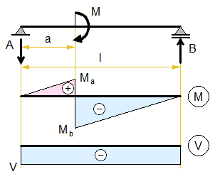
Concentrated moment \(M\) applied at distance \(a\), giving a constant shear \(V = M / l\) and a bending diagram with a step of \(M\) at the load section.
'<div style = "max-width:180mm;">
'<img style="width:190pt;" alt = "simply-supported-beam-concentrated-moment.png" class="side" src = "../../Images/mechanics/beams/simply-supported-beam-concentrated-moment.png">
'<p><b>Input data</b></p>
'Beam length -'l = ?'m
'Load -'M = ?'kN·m
'Distance -'a = ?'m
#post
'<p><b>Internal forces</b></p>
'Bending
M_a = M/l*a'kN·m
M_b = M/l*(l - a)'kN·m
'Shear
V = M/l'kN
'<p><b>Diagrams</b></p>
#hide
PlotWidth = 600
PlotHeight = 150
#show
'Calculate internal forces at'x_1 = ?'m
#pre
#post
'Bending
M(x) = -V*x + M*(x > a)
$Plot{-M(x) @ x = 0 : l}
M(x_1)'kN·m
'Shear
V(x) = V
$Plot{V(x) @ x = 0 : l}
V(x_1)'kN
#show
'</div>
5 10 2 1
Input data
Beam length - l = 5 m
Load - M = 10 kN·m
Distance - a = 2 m
Internal forces
Bending
Ma = Ml · a = 105 · 2 = 4 kN·m
Mb = Ml · ( l − a ) = 105 · ( 5 − 2 ) = 6 kN·m
Shear
V = Ml = 105 = 2 kN
Diagrams
Calculate internal forces at x1 = 1 m
Bending
M ( x ) = -V · x + M · ( x > a )

M ( x1 ) = M ( 1 ) = -2 kN·m
Shear
V ( x ) = V

V ( x1 ) = V ( 1 ) = 2 kN
Spotted an error? Edit these examples.