Reinforced Concrete¶
CalcpadCE worksheets in this section handle the verification and design of reinforced concrete members at ultimate and serviceability limit states according to Eurocode EN 1992-1-1 — bending, shear, torsion, axial force and their combinations on rectangular and T-cross-sections.
Bending of beams is treated separately for rectangular and T-sections, with a dedicated worksheet for the bending capacity of a T-section given the reinforcement layout. Shear of rectangular sections covers the variable-strut-inclination model and the maximum strut compression check, and the combined bending, shear and torsion sheet adds the space-truss model for the torsional resistance.
Columns are verified for uniaxial and biaxial bending with axial force, with a parallel unit-aware variant and a full N-M interaction diagram generated by sweeping the neutral-axis depth.
Serviceability is addressed by stress, crack-width and deflection checks for rectangular and T-cross-sections, with the static scheme picked from a drop-down list. A small reinforcement-area picker returns the total area \(A_s\) for a chosen bar diameter and count.
Areas of Reinforcement Bars¶
Lookup table that returns the total reinforcement area \(A_s\) for a chosen bar diameter and bar count, with the cells highlighting the picked combination on hover.
'<style>td:hover {color:red;} table {cursor:default;}</style>
'Required reinforcement area -'A_s,req = ? {7}'cm²
#pre
'<img style="height:104pt; width:122pt;" src="../../Images/structures/rc/design/bars.png" alt="bars.png">
#post
#val
'<table class="bordered">
'<tr><th>Count</th><!--'i = 0''j = 0'-->
#Repeat 10
    '<th id="c'j = j + 1'">'i = i + 1'</th>
    #if i ≡ 6
        '<th id="c'j = j + 1'">'20/3'</th>
    #else if i ≡ 8
        '<th id="c'j = j + 1'">'25/3'</th>
    #end if
#Loop
'</tr><!--'d = 6''j = 0'-->
#Repeat 11
    '<!--'i = 0''j = j + 1'--><tr><th id="r'j'">Ø'd = if(d ≡ 28; 32; if(d ≥ 22; d + 3; d + 2))'</th>
    #Repeat 10
        #hide
        i = i + 1
        A_s = π*d*d/400*i
        #post
        #if A_s > A_s,req
            '<td style="background:#EAFFCA" align="right">'A_s'</td>
        #else
            '<td align="right">'A_s'</td>
        #end if
        #if i ≡ 6
            #hide
            A_s = π*d*d/400*20/3
            #post
            #if A_s > A_s,req
                '<td style="background:#EAFFCA" align="right">'A_s'</td>
            #else
                '<td align="right">'A_s'</td>
            #end if
        #else if i ≡ 8
            #hide
            A_s = π*d*d/400*25/3
            #post
            #if A_s > A_s,req
                '<td style="background:#EAFFCA" align="right">'A_s'</td>
            #else
                '<td align="right">'A_s'</td>
            #end if
        #end if
    #Loop
#Loop
'</table>
'<script>var col=0;var row=0;$("td").hover(function(){$("#r"+row+",#c"+col).css("color","black").css("background-color","#F0F0F0");col=$(this).parent().children().index($(this));row=$(this).parent().parent().children().index($(this).parent());$("#r"+row+",#c"+col).css("color","red").css("background-color","#FFF0A0");;});</script>
Required reinforcement area - As,req = 7 cm²
| Count | 1 | 2 | 3 | 4 | 5 | 6 | 6.67 | 7 | 8 | 8.33 | 9 | 10 |
|---|---|---|---|---|---|---|---|---|---|---|---|---|
| Ø8 | 0.5 | 1.01 | 1.51 | 2.01 | 2.51 | 3.02 | 3.35 | 3.52 | 4.02 | 4.19 | 4.52 | 5.03 |
| Ø10 | 0.79 | 1.57 | 2.36 | 3.14 | 3.93 | 4.71 | 5.24 | 5.5 | 6.28 | 6.54 | 7.07 | 7.85 |
| Ø12 | 1.13 | 2.26 | 3.39 | 4.52 | 5.65 | 6.79 | 7.54 | 7.92 | 9.05 | 9.42 | 10.18 | 11.31 |
| Ø14 | 1.54 | 3.08 | 4.62 | 6.16 | 7.7 | 9.24 | 10.26 | 10.78 | 12.32 | 12.83 | 13.85 | 15.39 |
| Ø16 | 2.01 | 4.02 | 6.03 | 8.04 | 10.05 | 12.06 | 13.4 | 14.07 | 16.08 | 16.76 | 18.1 | 20.11 |
| Ø18 | 2.54 | 5.09 | 7.63 | 10.18 | 12.72 | 15.27 | 16.96 | 17.81 | 20.36 | 21.21 | 22.9 | 25.45 |
| Ø20 | 3.14 | 6.28 | 9.42 | 12.57 | 15.71 | 18.85 | 20.94 | 21.99 | 25.13 | 26.18 | 28.27 | 31.42 |
| Ø22 | 3.8 | 7.6 | 11.4 | 15.21 | 19.01 | 22.81 | 25.34 | 26.61 | 30.41 | 31.68 | 34.21 | 38.01 |
| Ø25 | 4.91 | 9.82 | 14.73 | 19.63 | 24.54 | 29.45 | 32.72 | 34.36 | 39.27 | 40.91 | 44.18 | 49.09 |
| Ø28 | 6.16 | 12.32 | 18.47 | 24.63 | 30.79 | 36.95 | 41.05 | 43.1 | 49.26 | 51.31 | 55.42 | 61.58 |
| Ø32 | 8.04 | 16.08 | 24.13 | 32.17 | 40.21 | 48.25 | 53.62 | 56.3 | 64.34 | 67.02 | 72.38 | 80.42 |
Bending Capacity of Tee Section¶
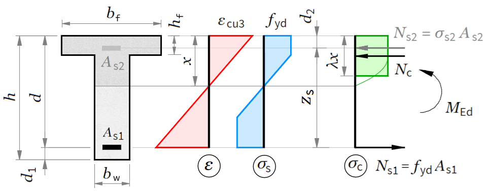
Bending capacity \(M_{Rd}\) of a T-cross-section with given reinforcement: rectangular stress block, neutral-axis depth from horizontal equilibrium and lever arm to the resultant of the compressed concrete.
'<small>According to <strong>Eurocode</strong>: EN 1992-1-1</small>
'<div style="max-width:180mm">
'<img style="width:400pt;" src="../../Images/structures/rc/design/tbeam-bending.png" alt="tbeam-bending.png">
'Design bending moment -'M_Ed = ?'kN·m
'<h4>Cross section dimensions</h4>
'Web -'b_w = ?'mm,'h_w = ?'mm
'Flange -'b_f = ?'mm,'h_f = ?'mm
#post
'Flange area -'A_f = (b_f - b_w)*h_f'mm²
'Section area -'A_c = b_w*h_w + A_f'mm²
#show
'<p><b>Concrete cover to the center of reinforcement</b></p>
'Bottom -'d_1 = ?'mm, Top -'d_2 = ?'mm
#post
'Effective cross section depth -'d = h_w - d_1'mm
#show
'<p><b>Reinforcement</b></p>
'Bottom -'A_s1 = ?'mm², Top -'A_s2 = ?'mm²
#post
'Reinforcement ratios
'- bottom reinforcement -'ρ_1 = (A_s1)/(b_w*d)
'- top reinforcement -'ρ_2 = (A_s2)/(b_w*d)
#show
'<h4>Material properties</h4>
'<p class="ref" style="float:right">[EN 1992-1-1, Table 3.1]</p>
'<p><b>Concrete</b></p>
'Characteristic compressive cylinder strength -'f_ck = ?'MPa
'Partial safety factor for concrete -'γ_c = 1.5','α_cc = ?
#post
'Design compressive cylinder strength -'f_cd = α_cc*f_ck/γ_c'MPa
'Ultimate compressive strain -'ε_cu2 = 0.0035
'Strain at the end of the parabolic part of the diagram -'ε_c2 = 0.002
'Mean value of axial tensile strength -'f_ctm = 0.30*f_ck^(2/3)'MPa
#show
'<p><b>Steel</b></p>
'Characteristic yield strength -'f_yk = ?'MPa
#post
'Partial safety factor for steel -'γ_s = 1.15
'Design yield strength -'f_yd = f_yk/γ_s'MPa
'Modulus of elasticity -'E_s = 200'GPa
'<p><b>Strain-stress diagrams</b>, MPa:</p>
'<!--'PlotWidth = 250','PlotHeight = 125'-->
'<table><tr><td>
#hide
n = 2
σ_c(ε) = f_cd*((1 - (1 - ε/ε_c2)^n)*(ε < ε_c2) + (ε ≥ ε_c2))
#post
$Plot{σ_c(ε/1000) @ ε = 0 : ε_cu2*1000}
'</td><td>
#hide
σ_s(ε) = max(-f_yd; min(ε*E_s*1000;f_yd))
#post
$Plot{σ_s(ε/1000) @ ε = -10 : 10}
'</td></tr></table>
'<h4>Design checks</h4>
'<p class="ref">[EN 1992-1-1, § 9.2.1.1]
'Minimum tensile reinforcement ratio
ρ_min = max(0.26*f_ctm/f_yk;0.0013)
#if ρ_1 < ρ_min
'<p class="err">Tensile reinforcement ratio is lower than minimum:'ρ_1'<'ρ_min'</p>'
#end if
'Maximum tensile reinforcement ratio -'ρ_max = 0.04
#if ρ_1 > ρ_max
'<p class="err">Tensile reinforcement ratio is greater than maximum:'ρ_1'>'ρ_max'</p>'
#end if
'Internal section forces as a function of the compressive zone depth <i>x</i>.
'Reinforcement strain:
'- in bottom reinforcement -'ε_s1(x) = ε_cu2*(d - x)/x
'- in top reinforcement -'ε_s2(x) = ε_cu2*(d_2 - x)/x
'- at flange bottom edge -'ε_cf(x) = ε_cu2*(x - h_f)/x
'Factors for integration of concrete stress diagram
k = f_cd*ε_cu2
k_1(ε_cu) = $Area{σ_c(ε)/k @ ε = 0 : ε_cu}
k_2(ε_cu) = $Area{σ_c(ε)*ε/(ε_cu2*k) @ ε = 0 : ε_cu}
k_1 = k_1(ε_cu2)
k_2 = k_2(ε_cu2)
'Internal section forces:
'- in concrete -'N_c(x) = -(k_1*x*b_f*(x < h_f) + (k_1*x*b_f - k_1(ε_cf(x))*(x - h_f)*(b_f - b_w))*(x ≥ h_f))*f_cd*10^-3
'- in bottom reinforcement -'N_s1(x) = σ_s(ε_s1(x))*A_s1*10^-3
'- in top reinforcement -'N_s2(x) = σ_s(ε_s2(x))*A_s2*10^-3
'Section capacity for axial force
N_Rd(x) = N_c(x) + N_s1(x) + N_s2(x)
$Plot{N_Rd(x) @ x = 0.1 : h_w}
'Compression zone depth is determined from the equilibrium of axial forces
x = $Root{N_Rd(x) @ x = 0.1 : h_w}'mm
'Compression zone depth at reinforcement yield point
x_lim = d* ε_cu2/(ε_cu2 + f_yd/E_s*10^-3)'cm
#if x ≤ x_lim
'Check:'x'≤'x_lim'- compressive reinforcement is not required.
#else
'Check:'x'>'x_lim'- compressive reinforcement is required.
#end if
'Distance to the equivalent concrete stress force
'- from the neutral line
#if x < h_f
z_0 = k_2/k_1*x'cm
#else
z_0 = (k_2*x^2*b_f - k_2(ε_cf(x))*(x - h_f)^2*(b_f - b_w))/(k_1*x*b_f - k_1(ε_cf(x))*(x - h_f)*(b_f - b_w))'cm
#end if
'- from the bottom edge of the section
z_c = h_w - x + z_0'mm
'Bending moment capacity
M_Rd = (A_s1*σ_s(ε_s1(x))*(z_c - d_1) + A_s2*σ_s(ε_s2(x))*(z_c - h_w + d_2))*10^-6'kN·m
#if M_Ed > M_Rd
'Design bending moment is greater than bending capacity
M_Ed'>'M_Rd'kN·m
'<p class="err">Design checks are NOT satisfied.</p>
#else
'Design bending moment is lower than bending capacity:
M_Ed'≤'M_Rd'kN·m
'Design checks are satisfied.
#end if
#show
'</div>
800 300 650 1200 120 50 50 3700 0 20 0.85 500
Design bending moment - MEd = 800 kN·m
Web - bw = 300 mm, hw = 650 mm
Flange - bf = 1200 mm, hf = 120 mm
Flange area - Af = ( bf − bw ) · hf = ( 1200 − 300 ) · 120 = 108000 mm²
Section area - Ac = bw · hw + Af = 300 · 650 + 108000 = 303000 mm²
Concrete cover to the center of reinforcement
Bottom - d1 = 50 mm, Top - d2 = 50 mm
Effective cross section depth - d = hw − d1 = 650 − 50 = 600 mm
Reinforcement
Bottom - As1 = 3700 mm², Top - As2 = 0 mm²
Reinforcement ratios
- bottom reinforcement - ρ1 = As1bw · d = 3700300 · 600 = 0.0206
- top reinforcement - ρ2 = As2bw · d = 0300 · 600 = 0
[EN 1992-1-1, Table 3.1]
Concrete
Characteristic compressive cylinder strength - fck = 20 MPa
Partial safety factor for concrete - γc = 1.5 , αcc = 0.85
Design compressive cylinder strength - fcd = αcc · fckγc = 0.85 · 201.5 = 11.33 MPa
Ultimate compressive strain - εcu2 = 0.0035
Strain at the end of the parabolic part of the diagram - εc2 = 0.002
Mean value of axial tensile strength - fctm = 0.3 · fck23 = 0.3 · 2023 = 2.21 MPa
Steel
Characteristic yield strength - fyk = 500 MPa
Partial safety factor for steel - γs = 1.15
Design yield strength - fyd = fykγs = 5001.15 = 434.78 MPa
Modulus of elasticity - Es = 200 GPa
Strain-stress diagrams, MPa:
 |
 |
[EN 1992-1-1, § 9.2.1.1]
Minimum tensile reinforcement ratio
ρmin = max(0.26 · fctmfyk; 0.0013) = max(0.26 · 2.21500; 0.0013) = 0.0013
Maximum tensile reinforcement ratio - ρmax = 0.04
Internal section forces as a function of the compressive zone depth x.
Reinforcement strain:
- in bottom reinforcement - εs1 ( x ) = εcu2 · ( d − x ) x
- in top reinforcement - εs2 ( x ) = εcu2 · ( d2 − x ) x
- at flange bottom edge - εcf ( x ) = εcu2 · ( x − hf ) x
Factors for integration of concrete stress diagram
k = fcd · εcu2 = 11.33 · 0.0035 = 0.0397
k1 ( εcu ) = εcu∫0 σc ( ε ) k dε
k2 ( εcu ) = εcu∫0 σc ( ε ) · εεcu2 · k dε
k1 = k1 ( εcu2 ) = k1 ( 0.0035 ) = 0.81
k2 = k2 ( εcu2 ) = k2 ( 0.0035 ) = 0.473
Internal section forces:
- in concrete - Nc ( x ) = - ( k1 · x · bf · ( x < hf ) + ( k1 · x · bf − k1 ( εcf ( x ) ) · ( x − hf ) · ( bf − bw ) ) · ( x ≥ hf ) ) · fcd · 10-3
- in bottom reinforcement - Ns1 ( x ) = σs ( εs1 ( x ) ) · As1 · 10-3
- in top reinforcement - Ns2 ( x ) = σs ( εs2 ( x ) ) · As2 · 10-3
Section capacity for axial force
NRd ( x ) = Nc ( x ) + Ns1 ( x ) + Ns2 ( x )

Compression zone depth is determined from the equilibrium of axial forces
x = $Root{NRd ( x ) = 0; x ∈ [0.1; hw]} = 147.5 mm
Compression zone depth at reinforcement yield point
xlim = d · εcu2εcu2 + fydEs · 10-3 = 600 · 0.00350.0035 + 434.78200 · 10-3 = 370.11 cm
Check: x = 147.5 ≤ xlim = 370.11 - compressive reinforcement is not required.
Distance to the equivalent concrete stress force
- from the neutral line
z0 = k2 · x2 · bf − k2 ( εcf ( x ) ) · ( x − hf ) 2 · ( bf − bw ) k1 · x · bf − k1 ( εcf ( x ) ) · ( x − hf ) · ( bf − bw ) = 0.473 · 147.52 · 1200 − k2 ( εcf ( 147.5 ) ) · ( 147.5 − 120 ) 2 · ( 1200 − 300 ) 0.81 · 147.5 · 1200 − k1 ( εcf ( 147.5 ) ) · ( 147.5 − 120 ) · ( 1200 − 300 ) = 86.93 cm
- from the bottom edge of the section
zc = hw − x + z0 = 650 − 147.5 + 86.93 = 589.43 mm
Bending moment capacity
MRd = ( As1 · σs ( εs1 ( x ) ) · ( zc − d1 ) + As2 · σs ( εs2 ( x ) ) · ( zc − hw + d2 ) ) · 10-6 = ( 3700 · σs ( εs1 ( 147.5 ) ) · ( 589.43 − 50 ) + 0 · σs ( εs2 ( 147.5 ) ) · ( 589.43 − 650 + 50 ) ) · 10-6 = 867.77 kN·m
Design bending moment is lower than bending capacity:
MEd = 800 ≤ MRd = 867.77 kN·m
Design checks are satisfied.
Bending Design of Rectangular Section¶
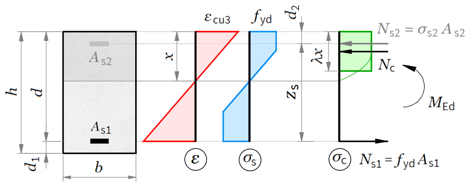
Required tension reinforcement \(A_s\) of a rectangular section under a design moment \(M_{Ed}\), with compression reinforcement added when the relative neutral-axis depth exceeds the ductility limit.
'<small>According to <strong>Eurocode</strong>: EN 1992-1-1</small>
'<div style = "max-width:180mm;">
'<img style="width:330pt;" src="../../Images/structures/rc/design/beam-bending.png" alt="beam-bending.png">
'Design bending moment -'M_Ed = ? {340}'kN·m
'<h4>Cross section dcimensions</h4>
'Width -'b = ? {300}'mm, Height -'h = ? {500}'mm
'Concrete cover to the center of reinforcement -'d_1 = ? {50}'mm
#post
'Effective cross section depth -'d = h - d_1'cm
#show
'<h4>Material properties</h4>
'<p class="ref" style="float:right">[EN 1992-1-1, Table 3.1]</p>
'<p><b>Concrete</b></p>
'Characteristic compressive cylinder strength -'f_ck = ? {20}'MPa
'Partial safety factor for concrete -'γ_c = 1.5','α_cc = ? {0.85}
#post
'Design compressive cylinder strength -'f_cd = α_cc*f_ck/γ_c'MPa
'Factor for effective compression zone depth -'λ = 0.8
'Effective compressive strength factor -'η = 1.0
'Ultimate compressive strain -'ε_cu3 = 0.0035
'Mean value of axial tensile strength -'f_ctm = 0.30*f_ck^(2/3)'MPa
#show
'<p><b>Steel</b></p>
'Characteristic yield strength -'f_yk = ? {500}'MPa
#post
'Partial safety factor for steel -'γ_s = 1.15
'Design yield strength -'f_yd = f_yk/γ_s'MPa
'Modulus of elasticity -'E_s = 200000'MPa
'<h4>Bending design</h4>
'Relative design bending moment -'m_Ed = M_Ed*10^6/(b*d^2*η*f_cd)
'Compression zone depth -'x = d/λ*(1 - sqr(1 - 2*m_Ed))'mm
'Relative compression zone depth -'ξ = x/d'
'Design reinforcement yield strain
ε_yd = f_yd/E_s
'Relative depth of compression zone at yielding of bottom reinforcement
ξ_yd = ε_cu3/(ε_cu3 + ε_yd)
#show
'Limit compression zone depth -'ξ_lim = ? {0.62}
'(enter <i>ξ</i><sub>yd</sub> for elastic or 0.45 for plastic analysis)
#post
#if ξ ≤ ξ_lim
ξ'≤'ξ_lim'- Compressive reinforcement is NOT required.
'Lever arm of internal forces -'z = d - 0.5*λ*x'mm
'Area of required tensile reinforcement -'A_s1 = M_Ed*10^6/(z*f_yd)'mm²
'Reinforcement ratio
ρ_1 = A_s1/(b*d)
ρ_2 = 0
#else
ξ'>'ξ_lim'- Compressive reinforcement is required.
'Relative depth is assumed to be'ξ = ξ_lim'and compressive reinforcement is designed
'Compression zone depth -'x = ξ*d'mm
'Distance from the center of compressive reinforcement to the concrete surface
d_2 = h - d'mm
'Distance between tensile and compressive reinforcement -'z_s = d - d_2'mm
'Resultant compression force in concrete
N_c = b*λ*x*η*f_cd*10^-3'kN
'Required tensile reinforcement area:
A_s1 = (M_Ed*10^6 + N_c*10^3*(λ*x/2 - d_2))/(f_yd*z_s)'mm²
'Compressive reinforcement strain
ε_s2 = (x - d_2)/x*ε_cu3
'Compressive reinforcement stress
σ_s2 = min(ε_s2*E_s; f_yd)'MPa
'Required compressive reinforcement area:
A_s2 = (M_Ed*10^6 - N_c*10^3*(d - λ*x/2))/(σ_s2*z_s)'mm²
'Reinforcement ratio:
'- tensile reinforcement -'ρ_1 = A_s1/(b*d)
'- compressive reinforcement -'ρ_2 = A_s2/(b*d)
#end if
'<p class="ref">[EN 1992-1-1, § 9.2.1.1]</p>
'Minimum tensile reinforcement ratio
ρ_min = max(0.26*f_ctm/f_yk; 0.0013)
'Minimum area of tensile reinforcement -'A_s_min = ρ_min*b*d'mm²
#if A_s1 < A_s_min
'<p class="err">Required reinforcement is lower than minimum:'A_s1'mm² <'A_s_min'mm²</p>'
#end if
'<p class="ref">[EN 1992-1-1, § 9.2.1.1]</p>
'Maximum tensile reinforcement ratio -'ρ_max = 0.04
#if ρ_1 > ρ_max
'<p class="err">Tensile reinforcement ratio is greater than maximum:'ρ_1'>'ρ_max'</p>'
#end if
#if ρ_2 > ρ_max
'<p class="err">Compressive reinforcement ratio is greater than maximum:'ρ_2'>'ρ_max'</p>'
#end if
#show
'</div>
Design bending moment - MEd = 340 kN·m
Width - b = 300 mm, Height - h = 500 mm
Concrete cover to the center of reinforcement - d1 = 50 mm
Effective cross section depth - d = h − d1 = 500 − 50 = 450 cm
[EN 1992-1-1, Table 3.1]
Concrete
Characteristic compressive cylinder strength - fck = 20 MPa
Partial safety factor for concrete - γc = 1.5 , αcc = 0.85
Design compressive cylinder strength - fcd = αcc · fckγc = 0.85 · 201.5 = 11.33 MPa
Factor for effective compression zone depth - λ = 0.8
Effective compressive strength factor - η = 1
Ultimate compressive strain - εcu3 = 0.0035
Mean value of axial tensile strength - fctm = 0.3 · fck23 = 0.3 · 2023 = 2.21 MPa
Steel
Characteristic yield strength - fyk = 500 MPa
Partial safety factor for steel - γs = 1.15
Design yield strength - fyd = fykγs = 5001.15 = 434.78 MPa
Modulus of elasticity - Es = 200000 MPa
Relative design bending moment - mEd = MEd · 106b · d2 · η · fcd = 340 · 106300 · 4502 · 1 · 11.33 = 0.494
Compression zone depth - x = dλ · ( 1 − √ 1 − 2 · mEd ) = 4500.8 · ( 1 − √ 1 − 2 · 0.494 ) = 500 mm
Relative compression zone depth - ξ = xd = 500450 = 1.11
Design reinforcement yield strain
εyd = fydEs = 434.78200000 = 0.00217
Relative depth of compression zone at yielding of bottom reinforcement
ξyd = εcu3εcu3 + εyd = 0.00350.0035 + 0.00217 = 0.617
Limit compression zone depth - ξlim = 0.62
(enter ξyd for elastic or 0.45 for plastic analysis)
ξ = 1.11 > ξlim = 0.62 - Compressive reinforcement is required.
Relative depth is assumed to be ξ = ξlim = 0.62 and compressive reinforcement is designed
Compression zone depth - x = ξ · d = 0.62 · 450 = 279 mm
Distance from the center of compressive reinforcement to the concrete surface
d2 = h − d = 500 − 450 = 50 mm
Distance between tensile and compressive reinforcement - zs = d − d2 = 450 − 50 = 400 mm
Resultant compression force in concrete
Nc = b · λ · x · η · fcd · 10-3 = 300 · 0.8 · 279 · 1 · 11.33 · 10-3 = 758.88 kN
Required tensile reinforcement area:
As1 = MEd · 106 + Nc · 103 · (λ · x2 − d2)fyd · zs = 340 · 106 + 758.88 · 103 · (0.8 · 2792 − 50)434.78 · 400 = 2223.8 mm²
Compressive reinforcement strain
εs2 = x − d2x · εcu3 = 279 − 50279 · 0.0035 = 0.00287
Compressive reinforcement stress
σs2 = min ( εs2 · Es; fyd ) = min ( 0.00287 · 200000; 434.78 ) = 434.78 MPa
Required compressive reinforcement area:
As2 = MEd · 106 − Nc · 103 · (d − λ · x2)σs2 · zs = 340 · 106 − 758.88 · 103 · (450 − 0.8 · 2792)434.78 · 400 = 478.37 mm²
Reinforcement ratio:
- tensile reinforcement - ρ1 = As1b · d = 2223.8300 · 450 = 0.0165
- compressive reinforcement - ρ2 = As2b · d = 478.37300 · 450 = 0.00354
[EN 1992-1-1, § 9.2.1.1]
Minimum tensile reinforcement ratio
ρmin = max(0.26 · fctmfyk; 0.0013) = max(0.26 · 2.21500; 0.0013) = 0.0013
Minimum area of tensile reinforcement - As_min = ρmin · b · d = 0.0013 · 300 · 450 = 175.5 mm²
[EN 1992-1-1, § 9.2.1.1]
Maximum tensile reinforcement ratio - ρmax = 0.04
Bending Design of Tee Section¶
Required tension reinforcement \(A_s\) of a T-section under a design moment \(M_{Ed}\), switching between rectangular flange-only behaviour and T-section behaviour according to the position of the neutral axis.
'<small>According to <strong>Eurocode</strong>: EN 1992-1-1</small>
'<div style="max-width:180mm;">
'<img style="width:400pt;" src="../../Images/structures/rc/design/tbeam-bending.png" alt="tbeam-bending.png">
'Design bending moment -'M_Ed = ?'kN·m
'<h4>Cross section dimensions</h4>
'Web -'b_w = ?'mm,'h_w = ?'mm
'Flange -'b_f = ?'mm,'h_f = ?'mm
'Concrete cover to the center of reinforcement -'d_1 = ?'mm
#post
'Effective cross section depth -'d = h_w - d_1'mm
'Flange area -'A_f = (b_f - b_w)*h_f'mm<sup>2</sup>
'Flange first moment of area -'S_f = A_f*(d - h_f/2)'mm<sup>3</sup>
#show
'<h4>Material properties</h4>
'<p class="ref" style="float:right">[EN 1992-1-1, Table 3.1]</p>
'<p><b>Concrete</b></p>
'Characteristic compressive cylinder strength -'f_ck = ?'MPa
'Partial safety factor for concrete -'γ_c = 1.5','α_cc = ?
#post
'Design compressive cylinder strength -'f_cd = α_cc*f_ck/γ_c'MPa
'Factor for effective compression zone depth -'λ = 0.8
'Effective compressive strength factor -'η = 1.0
'Ultimate compressive strain -'ε_cu3 = 0.0035
'Mean value of axial tensile strength -'f_ctm = 0.30*f_ck^(2/3)'MPa
#show
'<p><b>Steel</b></p>
'Characteristic yield strength -'f_yk = ?'MPa
#post
'Partial safety factor for steel -'γ_s = 1.15
'Design yield strength -'f_yd = f_yk/γ_s'MPa
'Modulus of elasticity -'E_s = 200000'MPa
'<h4>Bending design</h4>
'Check for the location of the neutral line
'Bending moment for neutral line at the bottom edge of the flange
M_f = b_f*h_f*η*f_cd*(d - h_f/2)*10^-6'kN·m
#if M_Ed > M_f
'The neutral line is below the flange - design for T-section
'Relative design bending moment -'m_Ed = M_Ed*10^6/(b_w*d^2*η*f_cd)
'Compression zone depth -'x = d/λ*(1 - sqr(1 - 2*(m_Ed - S_f/(b_w*d^2))))'mm
'Relative compression zone depth -'ξ = x/d'
'Design yield strain of reinforcement -'ε_yd = f_yd/E_s
'Relative depth of compression zone corresponding to design yield strain
ξ_yd = ε_cu3/(ε_cu3 + ε_yd)
#show
'Limit compression zone depth -'ξ_lim = ?
'(enter <i>ξ</i><sub>yd</sub> for elastic or 0.45 for plastic analysis)
#post
#if ξ ≤ ξ_lim
ξ'≤'ξ_lim'- compressive reinforcement is NOT required.
'Lever arm of internal forces -'z = d - 0.5*λ*x'mm
'Required tensile reinforcement area -'A_s1 = M_Ed*10^6/(z*f_yd)'mm<sup>2</sup>
'Reinforcement ratio -'ρ_1 = A_s1/(b_w*d)
'<!--'ρ_2 = 0'-->
#else
ξ'>'ξ_lim'- compressive reinforcement is required.
'Relative depth is assumed to be'ξ = ξ_lim'and compressive reinforcement is designed
'Compression zone depth -'x = ξ*d'mm
'Distance from the center of compressive reinforcement to the concrete surface
d_2 = h_w - d'mm
'Distance between tensile and compressive reinforcement -'z_s = d - d_2'mm
'Required tensile reinforcement area
A_s1 = (M_Ed*10^6 + (b_w*λ*x*(λ*x/2 - d_2) + A_f*(h_f/2 - d_2))*η*f_cd)/(f_yd*z_s)'mm<sup>2</sup>
'Strain is compressive reinforcement
ε_s2 = (x - d_2)/x*ε_cu3
'Compressive reinforcement stress
σ_s2 = min(ε_s2*E_s; f_yd)'MPa
'Required compressive reinforcement area
A_s2 = (A_s1*f_yd - (b_w*λ*x + A_f)*η*f_cd)/σ_s2'mm<sup>2</sup>
'Reinforcement ratios
'- tensile reinforcement -'ρ_1 = A_s1/(b_w*d)
'- compressive reinforcement -'ρ_2 = A_s2/(b_w*d)
#end if
#else
'The neutral line is within the flange - design of rectangular section with'b_f'mm
'Relative design bending moment -'m_Ed = M_Ed*10^6/(b_f*d^2*η*f_cd)
'Compression zone depth -'x = d/λ*(1 - sqr(1 - 2*m_Ed))'mm
'Lever arm of internal forces -'z = d - 0.5*λ*x'mm
'Area of required tensile reinforcement -'A_s1 = M_Ed*10^6/(z*f_yd)'mm<sup>2</sup>
'Reinforcement ratio
ρ_1 = A_s1/(b_w*d)
'<!--'ρ_2 = 0'-->
#end if
'<p class="ref">[EN 1992-1-1, § 9.2.1.1]
'Minimum tensile reinforcement ratio
ρ_min = max(0.26*f_ctm/f_yk; 0.0013)
'Minimum reinforcement -'A_s_min = ρ_min*b_w*d'mm<sup>2</sup>
#if A_s1 < A_s_min
'<p class="err">The reinforcement is then the minimum:'A_s1'mm<sup>2</sup> <'A_s_min'mm<sup>2</sup></p>'
#end if
'Maximum reinforcement ratio -'ρ_max = 0.04
#if '<!--'ρ_1 > ρ_max'-->'
'<p class="err">Reinforcement ratio is greater than the maximum:'ρ_1'>'ρ_max'mm<sup>2</sup></p>'
#end if
#show
'</div>
800 250 600 1200 120 50 20 0.85 500 0.62
Design bending moment - MEd = 800 kN·m
Web - bw = 250 mm, hw = 600 mm
Flange - bf = 1200 mm, hf = 120 mm
Concrete cover to the center of reinforcement - d1 = 50 mm
Effective cross section depth - d = hw − d1 = 600 − 50 = 550 mm
Flange area - Af = ( bf − bw ) · hf = ( 1200 − 250 ) · 120 = 114000 mm2
Flange first moment of area - Sf = Af · (d − hf2) = 114000 · (550 − 1202) = 55860000 mm3
[EN 1992-1-1, Table 3.1]
Concrete
Characteristic compressive cylinder strength - fck = 20 MPa
Partial safety factor for concrete - γc = 1.5 , αcc = 0.85
Design compressive cylinder strength - fcd = αcc · fckγc = 0.85 · 201.5 = 11.33 MPa
Factor for effective compression zone depth - λ = 0.8
Effective compressive strength factor - η = 1
Ultimate compressive strain - εcu3 = 0.0035
Mean value of axial tensile strength - fctm = 0.3 · fck23 = 0.3 · 2023 = 2.21 MPa
Steel
Characteristic yield strength - fyk = 500 MPa
Partial safety factor for steel - γs = 1.15
Design yield strength - fyd = fykγs = 5001.15 = 434.78 MPa
Modulus of elasticity - Es = 200000 MPa
Check for the location of the neutral line
Bending moment for neutral line at the bottom edge of the flange
Mf = bf · hf · η · fcd · (d − hf2) · 10-6 = 1200 · 120 · 1 · 11.33 · (550 − 1202) · 10-6 = 799.68 kN·m
The neutral line is below the flange - design for T-section
Relative design bending moment - mEd = MEd · 106bw · d2 · η · fcd = 800 · 106250 · 5502 · 1 · 11.33 = 0.933
Compression zone depth - x = dλ · (1 − 1 − 2 · (mEd − Sfbw · d2)) = 5500.8 · (1 − 1 − 2 · (0.933 − 55860000250 · 5502)) = 150.33 mm
Relative compression zone depth - ξ = xd = 150.33550 = 0.273
Design yield strain of reinforcement - εyd = fydEs = 434.78200000 = 0.00217
Relative depth of compression zone corresponding to design yield strain
ξyd = εcu3εcu3 + εyd = 0.00350.0035 + 0.00217 = 0.617
Limit compression zone depth - ξlim = 0.62
(enter ξyd for elastic or 0.45 for plastic analysis)
ξ = 0.273 ≤ ξlim = 0.62 - compressive reinforcement is NOT required.
Lever arm of internal forces - z = d − 0.5 · λ · x = 550 − 0.5 · 0.8 · 150.33 = 489.87 mm
Required tensile reinforcement area - As1 = MEd · 106z · fyd = 800 · 106489.87 · 434.78 = 3756.11 mm2
Reinforcement ratio - ρ1 = As1bw · d = 3756.11250 · 550 = 0.0273
[EN 1992-1-1, § 9.2.1.1]
Minimum tensile reinforcement ratio
ρmin = max(0.26 · fctmfyk; 0.0013) = max(0.26 · 2.21500; 0.0013) = 0.0013
Minimum reinforcement - As_min = ρmin · bw · d = 0.0013 · 250 · 550 = 178.75 mm2
Maximum reinforcement ratio - ρmax = 0.04
Column Design for Bending and Axial Force¶
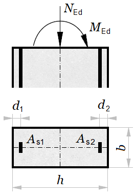
Verification of a rectangular reinforced concrete column under bending and axial force from the strain compatibility, with symmetric or asymmetric reinforcement and the strut compression check.
'<small>According to <strong>Eurocode</strong>: EN 1992-1-1</small>
'<div style="max-width:180mm">
'<img class="side" style="width:150pt;"src="../../Images/structures/rc/design/column-design.png" alt="column-design.png">
'<h4>Cross section dimensions</h4>
'Width -'b = ? {300}'mm, Height -'h = ? {700}'mm
#post
'Cross section area -'A_c = b*h'mm²
#show
'<p><b>Reinforcement area</b></p>
'Left -'A_s1 = ? {800}'mm², Right -'A_s2 = A_s1'mm²
#post
'Reinforcement ratio -'ρ = (A_s1 + A_s2)/A_c
#show
'<p><b>Concrete cover to the center of reinforcement</b></p>
'Left -'d_1 = ? {50}'mm, Right -'d_2 = d_1'mm
#post
'Effective cross section depth -'d = h - d_1'mm
#show
'<h4>Section design loads</h4>
'<table>
'<tr><td>№ 1 - </td><td>'M_Ed_1 = ? {100}'kN·m, </td><td>'N_Ed_1 = ? {500}'kN</td></tr>
'<tr><td>№ 2 - </td><td>'M_Ed_2 = ? {100}'kN·m, </td><td>'N_Ed_2 = ? {1000}'kN</td></tr>
'<tr><td>№ 3 - </td><td>'M_Ed_3 = ? {100}'kN·m, </td><td>'N_Ed_3 = ? {1500}'kN</td></tr>
'<tr><td>№ 4 - </td><td>'M_Ed_4 = ? {100}'kN·m, </td><td>'N_Ed_4 = ? {2000}'kN</td></tr>
'<tr><td>№ 5 - </td><td>'M_Ed_5 = ? {100}'kN·m, </td><td>'N_Ed_5 = ? {2500}'kN</td></tr>
'</table>
#pre
'All input values for M<sub>Ed</sub> and N<sub>Ed</sub> must be positive!
#show
'Positive axial force is compressive!
'<h4>Material properties</h4>
'<p class="ref" style="float:right">[EN 1992-1-1, Table 3.1]</p>
'<p><b>Concrete</b></p>
'Characteristic compressive cylinder strength -'f_ck = ? {20}'MPa
'Partial safety factor for concrete -'γ_c = 1.5','α_cc = ? {0.85}
#post
'Mean value of cylinder compressive strength -'f_cm = f_ck + 8'MPa
'Design compressive cylinder strength -'f_cd = α_cc*f_ck/γ_c'MPa
'Ultimate compressive strain -'ε_cu2 = 0.0035'('ε_c2 = 0.002','n = 2')'
'Secant modulus of elasticity -'E_cm = 22*(f_cm/10)^0.3'GPa
#show
'<p><b>Steel</b></p>
'Characteristic yield strength -'f_yk = ? {500}'MPa
#post
'Partial safety factor for steel -'γ_s = 1.15
'Design yield strength -'f_yd = f_yk/γ_s'MPa
'Modulus of elasticity -'E_s = 200'GPa
'<p><b>Strain-stress diagrams</b>, MPa:</p>
'<!--'PlotWidth = 250','PlotHeight = 125'-->
'<table><tr><td>
#hide
σ_c(ε) = f_cd*((1 - (1 - ε/ε_c2)^n)*(ε < ε_c2) + (ε ≥ ε_c2))
#post
$Plot{σ_c(ε/1000) @ ε = 0 : ε_cu2*1000}
'</td><td>
#hide
σ_s(ε) = max(-f_yd; min(ε*E_s*1000; f_yd))
#post
$Plot{σ_s(ε/1000) @ ε = -10 : 10}
'</td></tr></table>
#show
'<h4>Imperfections and second order effects</h4>
'Ratio of quasi-permanent bending moment: M<sub>0Eqp</sub>/M<sub>0Ed</sub> ='K_G = ? {0.75}
#post
'M<sub>0Eqp</sub> is the first order bending moment in quasi-permanent load combination (SLS)
'M<sub>0Ed</sub> is the first order bending moment in design load combination (ULS)
#show
'Long term creep factor - φ(∞,t<sub>0</sub>) ='φ = ? {2.5}
'Column height -'L = ? {4000}'mm
'Effective column height -'L_o = ? {2}*L'mm
'Number of vertical elements -'m = ? {1}
#hide
α_n_ = 2/sqr(L/1000)
α_n = max(2/3; min(α_n_; 1))
α_m = sqr(0.5*(1 + 1/m))
θ_o = 1/200
θ_i = θ_o*α_n*α_m
e_i_ = θ_i*L_o/2
e_o = max(h/30; 20)
e_i = max(e_i_; e_o)
I_c = (b*h^3)/12
i = sqr(I_c/A_c)
λ = L_o/i
k_1 = sqr(f_ck/20)
φ_ef = φ*K_G
K_s = 1
γ_cE = 1.3
E_cd = E_cm/γ_cE
I_s = A_s1*(h/2 - d_1)^2 + A_s2*(h/2 - d_2)^2
n(N) = N/(A_c*f_cd/1000)
k_2_(N) = n(N)*λ/170
k_2(N) = min(k_2_(N); 0.2)
K_c(N) = k_1*k_2(N)/(1 + φ_ef)
EI_e(N) = (K_c(N)*E_cd*I_c + K_s*E_s*I_s)
N_B(N) = π^2*EI_e(N)/(L_o)^2
#if L > 0
M_II_1 = (M_Ed_1 + N_Ed_1*e_i/1000)/(1 - N_Ed_1/N_B(N_Ed_1))
M_II_2 = (M_Ed_2 + N_Ed_2*e_i/1000)/(1 - N_Ed_2/N_B(N_Ed_2))
M_II_3 = (M_Ed_3 + N_Ed_3*e_i/1000)/(1 - N_Ed_3/N_B(N_Ed_3))
M_II_4 = (M_Ed_4 + N_Ed_4*e_i/1000)/(1 - N_Ed_4/N_B(N_Ed_4))
M_II_5 = (M_Ed_5 + N_Ed_5*e_i/1000)/(1 - N_Ed_5/N_B(N_Ed_5))
#else
M_II_1 = M_Ed_1
M_II_2 = M_Ed_2
M_II_3 = M_Ed_3
M_II_4 = M_Ed_4
M_II_5 = M_Ed_5
#end if
A_s_min = 0.002*A_c
#if A_s1 < A_s_min
A_s1 = A_s_min
#end if
#if A_s2 < A_s_min
A_s2 = A_s_min
#end if
ε_s1,a(x) = ε_cu2*(d - x)/x
ε_s2,a(x) = ε_cu2*(d_2 - x)/x
N_c,a(x) = 17/21*x*b*f_cd/1000
N_s1,a(x) = σ_s(ε_s1,a(x))*A_s1/1000
N_s2,a(x) = σ_s(ε_s2,a(x))*A_s2/1000
N_Rd,a(x) = N_c,a(x) - N_s1,a(x) - N_s2,a(x)
z_c,a(x) = h/2 - 99/238*x
M_Rd,a(x) = (N_c,a(x)*z_c,a(x) + N_s1,a(x)*(h/2 - d_1) - N_s2,a(x)*(h/2 - d_2))/1000
x(ε) = h*ε_cu2/(ε_cu2 + ε)
h_c = h*ε_c2/ε_cu2
ε_s1,b(ε) = ε + (ε_c2 - ε)*d_1/h_c
ε_s2,b(ε) = ε + (ε_c2 - ε)*(h - d_2)/h_c
N_c,b(ε) = (h_c/6*(σ_c(ε) + 4*σ_c((ε + ε_c2)/2) + σ_c(ε_c2)) + (h - h_c)*f_cd)*b/1000
N_s1,b(ε) = σ_s(ε_s1,b(ε))*A_s1/1000
N_s2,b(ε) = σ_s(ε_s2,b(ε))*A_s2/1000
N_Rd,b(ε) = N_c,b(ε) + N_s1,b(ε) + N_s2,b(ε)
M_c0(ε) = (h_c^2/6*(2*σ_c((ε + ε_c2)/2) + σ_c(ε_c2)) + (h^2 - h_c^2)/2*f_cd)*b/1000
z_c,b(ε) = M_c0(ε)/N_c,b(ε) - h/2
M_Rd,b(ε) = (N_c,b(ε)*z_c,b(ε) - N_s1,b(ε)*(h/2 - d_1) + N_s2,b(ε)*(h/2 - d_2))/1000
N_Rd(ε) = N_Rd,a(x(ε))*(ε ≥ 0) + N_Rd,b(abs(ε))*(ε < 0)
M_Rd(ε) = M_Rd,a(x(ε))*(ε ≥ 0) + M_Rd,b(abs(ε))*(ε < 0)
ε_max = $Root{N_Rd(ε) - 1 @ ε = 0 : 2}
#if ε_max > 0.1
ε_max = 0.1
#end if
N_Rd_max = A_c*f_cd/1000 + σ_s(ε_max)*(A_s1 + A_s2)/1000
#if N_Ed_1 > N_Rd_max
M_Rd_1 = 0
#else
ε_1 = $Root{N_Rd(ε) - N_Ed_1 @ ε = -ε_c2 : 2}
M_Rd_1 = M_Rd(ε_1)
#end if
#if N_Ed_2 > N_Rd_max
M_Rd_2 = 0
#else
ε_2 = $Root{N_Rd(ε) - N_Ed_2 @ ε = -ε_c2 : 2}
M_Rd_2 = M_Rd(ε_2)
#end if
#if N_Ed_3 > N_Rd_max
M_Rd_3 = 0
#else
ε_3 = $Root{N_Rd(ε) - N_Ed_3 @ ε = -ε_c2 : 2}
M_Rd_3 = M_Rd(ε_3)
#end if
#if N_Ed_4 > N_Rd_max
M_Rd_4 = 0
#else
ε_4 = $Root{N_Rd(ε) - N_Ed_4 @ ε = -ε_c2 : 2}
M_Rd_4 = M_Rd(ε_4)
#end if
#if N_Ed_5 > N_Rd_max
M_Rd_5 = 0
#else
ε_5 = $Root{N_Rd(ε) - N_Ed_5 @ ε = -ε_c2 : 2}
M_Rd_5 = M_Rd(ε_5)
#end if
M_Rd_ei(ε) = N_Rd(ε)*e_i/1000
M_Rd_II(ε) = M_Rd_ei(ε)/(1 - N_Rd(ε)/N_B(N_Rd(ε)))/(N_Rd(ε) < 0.95*N_B(N_Rd(ε)))
ε_ei = $Root{M_Rd_ei(ε) - M_Rd(ε) @ ε = -ε_c2 : ε_max}
M_Rd_ei = M_Rd(ε_ei)
N_Rd_ei = N_Rd(ε_ei)
#if N_Rd_max < N_B(N_Rd_max)
ε_NB = ε_ei
#else
ε_NB = $Root{N_Rd(ε) - 0.95*N_B(N_Rd(ε)) @ ε = -ε_c2 : ε_max}
#end if
ε_II = ε_NB
ε_II = $Root{M_Rd_ei(ε)/(1 - N_Rd(ε)/N_B(N_Rd(ε))) - M_Rd(ε) @ ε = ε_NB : ε_max}
M_Rd_II = M_Rd(ε_II)
N_Rd_II = N_Rd(ε_II)
PlotWidth = 600
PlotHeight = 600
#post
'<h4>Interaction diagram</h4>
'<p><i>N</i><sub>Rd</sub></p>
$Plot{M_Rd(ε)|N_Rd(ε) & M_Rd_ei(ε)|N_Rd(ε) & M_Rd_II(ε)|N_Rd(ε) & M_Rd_ei|N_Rd_ei & M_Rd_II|N_Rd_II & M_II_1|N_Ed_1 & M_II_2|N_Ed_2 & M_II_3|N_Ed_3 & M_II_4|N_Ed_4 & M_II_5|N_Ed_5 @ ε = ε_max : -ε_c2}
'<i>M</i><sub>Rd</sub>
'<p><b>Legend:</b></p>
'<p><b style="color:Tomato">━━</b> Interaction diagram</p>
'<p><b style="color:YellowGreen">━━</b> Line of geometric imperfections</p>
'<p><b style="color:CornflowerBlue">━━</b> Buckling curve</p>
'<p><b style="color:Gold">●</b> Design resistance including geometric imperfections and accidental eccentricity - <i>N</i><sub>Rd_ei</sub></p>
'<p><b style="color:MediumVioletRed">●</b> Design buckling resistance - <i>N</i><sub>Rd_II</sub></p>
'<p><b style="color:MediumSpringGreen">●</b> Design load № 1, <b style="color:BlueViolet">●</b> Design load № 2, <b style="color:LightSalmon">●</b> Design load № 3,</p>
'<p><b style="color:DeepPink">●</b> Design load № 4, <b style="color:DarkTurquoise">●</b> Design load № 5</p>
'<h4>Design checks</h4>
#val
'<table class="bordered centered">
'<tr><th>№</th><th>N<sub>Ed</sub><br/>kN</th><th></th><th>N<sub>B</sub><br/>kN</th><th>M<sub>Ed</sub><br/>kN·m</th><th>M<sub>II</sub><br/>kN·m</th><th> </th><th>M<sub>Rd</sub><br/>kN·m</th></tr>
#if N_Ed_1 > N_B(N_Ed_1)
'<tr class="err"><td>1</td><td>'N_Ed_1'</td><td>></td><td>'N_B(N_Ed_1)'</td><td></td><td></td><td></td><td></td></tr>
#else if M_Rd_1 > M_II_1
'<tr><td>1</td><td>'N_Ed_1'</td><td><</td><td>'N_B(N_Ed_1)'</td><td>'M_Ed_1'</td><td>'M_II_1'</td><td>≤</td><td>'M_Rd_1'</td></tr>
#else
'<tr class="err"><td>1</td><td>'N_Ed_1'</td><td><</td><td>'N_B(N_Ed_1)'</td><td>'M_Ed_1'</td><td>'M_II_1'</td><td>></td><td>'M_Rd_1'</td></tr>
#end if
#if N_Ed_2 > N_B(N_Ed_2)
'<tr class="err"><td>2</td><td>'N_Ed_2'</td><td>></td><td>'N_B(N_Ed_2)'</td><td></td><td></td><td></td><td></td></tr>
#else if M_Rd_2 > M_II_2
'<tr><td>2</td><td>'N_Ed_2'</td><td><</td><td>'N_B(N_Ed_2)'</td><td>'M_Ed_2'</td><td>'M_II_2'</td><td>≤</td><td>'M_Rd_2'</td></tr>
#else
'<tr class="err"><td>2</td><td>'N_Ed_2'</td><td><</td><td>'N_B(N_Ed_2)'</td><td>'M_Ed_2'</td><td>'M_II_2'</td><td>></td><td>'M_Rd_2'</td></tr>
#end if
#if N_Ed_3 > N_B(N_Ed_3)
'<tr class="err"><td>3</td><td>'N_Ed_3'</td><td>></td><td>'N_B(N_Ed_3)'</td><td></td><td></td><td></td><td></td></tr>
#else if M_Rd_3 > M_II_3
'<tr><td>3</td><td>'N_Ed_3'</td><td><</td><td>'N_B(N_Ed_3)'</td><td>'M_Ed_3'</td><td>'M_II_3'</td><td>≤</td><td>'M_Rd_3'</td></tr>
#else
'<tr class="err"><td>3</td><td>'N_Ed_3'</td><td><</td><td>'N_B(N_Ed_3)'</td><td>'M_Ed_3'</td><td>'M_II_3'</td><td>></td><td>'M_Rd_3'</td></tr>
#end if
#if N_Ed_4 > N_B(N_Ed_4)
'<tr class="err"><td>4</td><td>'N_Ed_4'</td><td>></td><td>'N_B(N_Ed_4)'</td><td></td><td></td><td></td><td></td></tr>
#else if M_Rd_4 > M_II_4
'<tr><td>4</td><td>'N_Ed_4'</td><td><</td><td>'N_B(N_Ed_4)'</td><td>'M_Ed_4'</td><td>'M_II_4'</td><td>≤</td><td>'M_Rd_4'</td></tr>
#else
'<tr class="err"><td>4</td><td>'N_Ed_4'</td><td><</td><td>'N_B(N_Ed_4)'</td><td>'M_Ed_4'</td><td>'M_II_4'</td><td>></td><td>'M_Rd_4'</td></tr>
#end if
#if N_Ed_5 > N_B(N_Ed_5)
'<tr class="err"><td>5</td><td>'N_Ed_5'</td><td>></td><td>'N_B(N_Ed_5)'</td><td></td><td></td><td></td><td></td></tr>
#else if M_Rd_5 > M_II_5
'<tr><td>5</td><td>'N_Ed_5'</td><td><</td><td>'N_B(N_Ed_5)'</td><td>'M_Ed_5'</td><td>'M_II_5'</td><td>≤</td><td>'M_Rd_5'</td></tr>
#else
'<tr class="err"><td>5</td><td>'N_Ed_5'</td><td><</td><td>'N_B(N_Ed_5)'</td><td>'M_Ed_5'</td><td>'M_II_5'</td><td>></td><td>'M_Rd_5'</td></tr>
#end if
'</table>
#equ
'<p><b>Ultimate capacity for axial force:</b></p>
'- cross section only -'N_Rd_max'kN
'- column with geometric imperfections -'N_Rd_ei'kN
'- column with imperfections and II order effects -'N_Rd_II'kN
'Buckling factor -'φ = N_Rd_II/N_Rd_max
#show
'</div>
Width - b = 300 mm, Height - h = 700 mm
Cross section area - Ac = b · h = 300 · 700 = 210000 mm²
Reinforcement area
Left - As1 = 800 mm², Right - As2 = As1 = 800 mm²
Reinforcement ratio - ρ = As1 + As2Ac = 800 + 800210000 = 0.00762
Concrete cover to the center of reinforcement
Left - d1 = 50 mm, Right - d2 = d1 = 50 mm
Effective cross section depth - d = h − d1 = 700 − 50 = 650 mm
| № 1 - | MEd_1 = 100 kN·m, | NEd_1 = 500 kN |
| № 2 - | MEd_2 = 100 kN·m, | NEd_2 = 1000 kN |
| № 3 - | MEd_3 = 100 kN·m, | NEd_3 = 1500 kN |
| № 4 - | MEd_4 = 100 kN·m, | NEd_4 = 2000 kN |
| № 5 - | MEd_5 = 100 kN·m, | NEd_5 = 2500 kN |
Positive axial force is compressive!
[EN 1992-1-1, Table 3.1]
Concrete
Characteristic compressive cylinder strength - fck = 20 MPa
Partial safety factor for concrete - γc = 1.5 , αcc = 0.85
Mean value of cylinder compressive strength - fcm = fck + 8 = 20 + 8 = 28 MPa
Design compressive cylinder strength - fcd = αcc · fckγc = 0.85 · 201.5 = 11.33 MPa
Ultimate compressive strain - εcu2 = 0.0035 ( εc2 = 0.002 , n = 2 )
Secant modulus of elasticity - Ecm = 22 · (fcm10)0.3 = 22 · (2810)0.3 = 29.96 GPa
Steel
Characteristic yield strength - fyk = 500 MPa
Partial safety factor for steel - γs = 1.15
Design yield strength - fyd = fykγs = 5001.15 = 434.78 MPa
Modulus of elasticity - Es = 200 GPa
Strain-stress diagrams, MPa:
|
|
|
Ratio of quasi-permanent bending moment: M0Eqp/M0Ed = KG = 0.75
M0Eqp is the first order bending moment in quasi-permanent load combination (SLS)
M0Ed is the first order bending moment in design load combination (ULS)
Long term creep factor - φ(∞,t0) = φ = 2.5
Column height - L = 4000 mm
Effective column height - Lo = 2 · L = 2 · 4000 = 8000 mm
Number of vertical elements - m = 1
NRd
 MRd
MRd
Legend:
━━ Interaction diagram
━━ Line of geometric imperfections
━━ Buckling curve
● Design resistance including geometric imperfections and accidental eccentricity - NRd_ei
● Design buckling resistance - NRd_II
● Design load № 1, ● Design load № 2, ● Design load № 3,
● Design load № 4, ● Design load № 5
| № | NEd kN | NB kN | MEd kN·m | MII kN·m | MRd kN·m | ||
|---|---|---|---|---|---|---|---|
| 1 | 500 | < | 4959.97 | 100 | 124.19 | ≤ | 345.91 |
| 2 | 1000 | < | 5478.61 | 100 | 150.87 | ≤ | 407.57 |
| 3 | 1500 | < | 5997.25 | 100 | 180.03 | ≤ | 358.3 |
| 4 | 2000 | < | 6515.9 | 100 | 211.62 | ≤ | 275.04 |
| 5 | 2500 | < | 6561.5 | 100 | 255.79 | > | 156.97 |
Ultimate capacity for axial force:
- cross section only - NRd_max = 3075.65 kN
- column with geometric imperfections - NRd_ei = 2840.45 kN
- column with imperfections and II order effects - NRd_II = 2690.81 kN
Buckling factor - φ = NRd_IINRd_max = 2690.813075.65 = 0.875
Column Design for Biaxial Bending and Axial Force¶
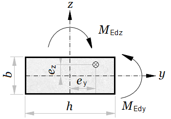
Verification of a rectangular reinforced concrete column under axial force and bending about both axes by superposition of the two uniaxial interaction surfaces with the EN 1992-1-1 power-law combination.
'<small>According to <strong>Eurocode</strong>: EN 1992-1-1</small>
'<div style="max-width:180mm">
'<img class="side" style="width:150pt;" src="../../Images/structures/rc/design/column-design.png" alt="column-design.png">
'<h4>Cross section dimensions</h4>
'Width -'b = ?'mm, Height -'h = ?'mm
#post
'Cross section area -'A_c = b*h'mm²
#show
'<p><b>Reinforcement</b></p>
'Left -'A_s1 = ?'mm², Right -'A_s2 = ?'mm²
#post
'Reinforcement ratio -'ρ = (A_s1 + A_s2)/A_c
#show
'<p><b>Concrete cover to the center of reinforcement</b></p>
'Left -'d_1 = ?'mm, Right -'d_2 = ?'mm
#post
'Effective cross section depth -'d = h - d_1'mm
#show
'<p><b>Section design loads</b></p>
'Axial force -'N_Ed = ?'kN (positive for compression)
'Bending moment -'M_Ed = ?'kN·m
'<h4>Material properties</h4>
'<p class="ref" style="float:right">[EN 1992-1-1, Table 3.1]</p>
'<p><b>Concrete</b></p>
'Characteristic compressive cylinder strength -'f_ck = ?'MPa
'Partial safety factor for concrete -'γ_c = 1.5','α_cc = ?
#post
'Design compressive cylinder strength -'f_cd = α_cc*f_ck/γ_c'MPa
'Mean value of cylinder compressive strength -'f_cm = f_ck + 8'MPa
'Secant modulus of elasticity -'E_cm = 22*(f_cm/10)^0.3'GPa
'Ultimate compressive strain -'ε_cu2 = 0.0035
'Strain at the end of parabolic part of the diagram -'ε_c2 = 0.002
#show
'<p><b>Steel</b></p>
'Characteristic yield strength -'f_yk = ?'MPa
#post
'Partial safety factor for steel -'γ_s = 1.15
'Design yield strength -'f_yd = f_yk/γ_s'MPa
'Modulus of elasticity -'E_s = 200'GPa
'<p><b>Strain-stress diagrams</b>, MPa:</p>
'<!--'PlotWidth = 250','PlotHeight = 125'-->
'<table><tr><td>
#hide
n = 2
σ_c(ε) = f_cd*((1 - (1 - ε/ε_c2)^n)*(ε < ε_c2) + (ε ≥ ε_c2))
#post
$Plot{σ_c(ε/1000) @ ε = 0 : ε_cu2*10^3}
'</td><td>
#hide
σ_s(ε) = max(-f_yd; min(ε*E_s*10^3;f_yd))
#post
$Plot{σ_s(ε/1000) @ ε = -10 : 10}
'</td></tr></table>
#show
'<h4>Imperfections and second order effects</h4>
'Ratio of quasi-permanent bending moment: M<sub>0Eqp</sub>/M<sub>0Ed</sub> ='K_G = ?
#post
'M<sub>0Eqp</sub> is the first order bending moment in quasi-permanent load combination (SLS)
'M<sub>0Ed</sub> is the first order bending moment in design load combination (ULS)
#show
'Long term creep factor - φ(∞,t<sub>0</sub>) ='φ = ?
'Column height -'L = ?'mm
'Effective column height -'L_o = ?*L'mm
#post
'<div class="fold">
#show
'<p><b>Geometric imperfections and accidental eccentricity</b></p>
'Number of vertical members contributing to the total effect -'m = ?
#post
'Reduction factor for height:
α_h_ = 2/sqr(L*10^-3)
'This value is limited within the interval: 2/3 ≤ α<sub>n</sub> ≤ 1
α_h = max(2/3;min(α_h_;1))
'Reduction factor for number of members
α_m = sqr(0.5*(1 + 1/m))
'Basic inclination value -'θ_o = 1/200
'<p class="ref">[EN 1992-1-1 (5.1)]</p>
'Inclination -'θ_i = θ_o*α_h*α_m
'<p class="ref">[EN 1992-1-1 (5.2)]</p>
'Eccentricity -'e_i_ = θ_i*L_o/2'mm
'<p class="ref">[EN 1992-1-1, § 6.1(4)]</p>
'Minimum eccentricity -'e_o_ = h/30'mm or 20 mm
e_o = max(e_o_;20)'mm
e_i = max(e_i_;e_o)'mm
'</div>
M_0Ed = M_Ed + N_Ed*e_i*10^-3'kN.m
'<div class="fold">
'<p><b>Second order effects based on the nominal stiffness method</b></p>
'Moment of inertia of the concrete cross section
I_c = (b*h^3)/12'mm<sup>4</sup>
'Radius of gyration
i = sqr(I_c/A_c)'mm
'Slenderness ratio
λ = L_o/i
'Relative axial force
n = N_Ed/(A_c*f_cd*10^-3)
'<p class="ref">[EN 1992-1-1 (5.23)]</p>
'Factor depending on the concrete strength class
k_1 = sqr(f_ck/20)
'<p class="ref">[EN 1992-1-1 (5.24)]</p>
'Factor depending on axial force and slenderness
k_2_ = n*λ/170
'Maximum value - k<sub>2</sub> < 0.20
k_2 = min(k_2_;0.20)
'Effective creep ratio
'φ<sub>ef</sub> = φ(∞,t0)·M<sub>0Eqp</sub>/M<sub>0Ed</sub>
φ_ef = φ*K_G
'<p class="ref">[EN 1992-1-1 (5.22)]</p>
K_c = k_1*k_2/(1 + φ_ef)'– factor for effects of cracking, creep etc.
K_s = 1'– factor for contribution of reinforcement
'Second moment of area of the reinforcement, about the centroid
I_s = A_s1*(h/2 - d_1)^2 + A_s2*(h/2 - d_2)^2'mm<sup>4</sup>
'<p class="ref">[BS EN 1992-1-1 (5.20), NA.1]</p>
γ_cE = 1.2
'<p class="ref">[EN 1992-1-1 (5.20)]</p>
'Design value of the modulus of elasticity of concrete
E_cd = E_cm/γ_cE'GPa
'<p class="ref">[EN 1992-1-1 (5.21)]</p>
'Nominal stiffness
EI = (K_c*E_cd*I_c + K_s*E_s*I_s)'kN·mm²
'<p class="ref">[EN 1992-1-1 (5.17)]</p>
'Buckling load
N_B = π^2*EI/(L_o)^2'kN
'</div>
'<p class="ref">[EN 1992-1-1 (5.30)]</p>
'Total design moment (including second order moment)
M_Ed = M_0Ed/(1 - N_Ed/N_B)'kN·m
'<h4>Design checks</h4>
'Design axial resistance of section when strain'ε = ε_c2
N_Rd_max = A_c*f_cd*10^-3 + σ_s(ε)*(A_s1 + A_s2)*10^-3'kN
#if N_Ed > N_Rd_max
'Design axial load is greater than the ultimate axial force capacity
N_Ed'>'N_Rd_max'kN
'<p class="err">The design check is NOT satisfied.</p>
#else
'Internal forces in the section are expressed as functions of the compression zone depth<i>x</i>.
'Reinforcement strain:
'- bottom reinforcement -'ε_s1(x) = ε_cu2*(d - x)/x
'- top reinforcement -'ε_s2(x) = ε_cu2*(d_2 - x)/x
'Internal forces:
'- concrete -'N_c(x) = 17/21*x*b*f_cd*10^-3
'- bottom reinforcement -'N_s1(x) = σ_s(ε_s1(x))*A_s1*10^-3
'- top reinforcement -'N_s2(x) = σ_s(ε_s2(x))*A_s2*10^-3
'Section resistance for axial force
N_Rd(x) = N_c(x) - N_s1(x) - N_s2(x)
'Axial force, corresponding to triangular strain distribution
N_Rd_h = N_Rd(h)'kN
#if N_Ed < N_Rd_h
'Section is partially in tension -'N_Ed'kN <'N_Rd_h'kN
'Compression zone depth is determined from the equilibrium of the axial forces in the section
x = $Root{N_Rd(x) - N_Ed @ x = d_2 : h}'mm
'Lever arm of concrete stress to the cross section centroid
z_c = h/2 - 99/238*x'mm
'Bending resistance at <i>N</i><sub>Ed</sub> = <i>N</i><sub>Rd</sub>
M_Rd = (N_c(x)*z_c + N_s1(x)*(h/2 - d_1) - N_s2(x)*(h/2 - d_2))*10^-3'kN·m
#else
'Section is entirely in compression -'N_Ed'≥'N_Rd_h'kN
'Distance from the point with constant strain to the bottom edge of the section
h_c = h*ε_c2/ε_cu2
'Internal forces are expressed as functions of the strain <i>ε</i> at the bottom edge.
'Reinforcement strain:
'- bottom reinforcement -'ε_s1(ε) = ε + (ε_c2 - ε)*d_1/h_c
'- top reinforcement -'ε_s2(ε) = ε + (ε_c2 - ε)*(h - d_2)/h_c
'Internal forces:
'- concrete -'N_c(ε) = (h_c/6*(σ_c(ε) + 4*σ_c((ε + ε_c2)/2) + σ_c(ε_c2)) + (h - h_c)*f_cd)*b*10^-3
'- bottom reinforcement -'N_s1(ε) = σ_s(ε_s1(ε))*A_s1*10^-3
'- top reinforcement -'N_s2(ε) = σ_s(ε_s2(ε))*A_s2*10^-3
'Section resistance for axial force
N_Rd(ε) = N_c(ε) + N_s1(ε) + N_s2(ε)
'Strain at bottom edge is determined from the equilibrium of the axial forces in the section
ε_c = $Root{N_Rd(ε) - N_Ed @ ε = 0 : ε_c2}
'Equivalent bending moment about the lower section edge, due to concrete stress
M_c0 = (h_c^2/6*(2*σ_c((ε_c + ε_c2)/2) + σ_c(ε_c2)) + (h^2 - h_c^2)/2*f_cd)*b*10^-3'kNm
'Lever arm of concrete stress equivalent force about the section centroid
z_c = M_c0/N_c(ε_c) - h/2'mm
'Bending resistance at <i>N</i><sub>Ed</sub> = <i>N</i><sub>Rd</sub>
M_Rd = (N_c(ε_c)*z_c - N_s1(ε_c)*(h/2 - d_1) + N_s2(ε_c)*(h/2 - d_2))*10^-3'kN·m
#end if
#if M_Ed > M_Rd
'Design bending is greater than the bending resistance:
M_Ed'>'M_Rd'kN·m
'<p class="err">The design check is NOT satisfied.</p>
#else
'Bending moment is less than moment resistance:
M_Ed'≤'M_Rd'kN·m
'The design check is satisfied.
#pre
'<img class="side" style="width:190pt;" src="../../Images/structures/rc/design/column-biaxial.png" alt="column-biaxial.png">
'<h4>Biaxial bending design</h4>
'For the other direction:
'Design moment -'M_Edy = ?'kN·m
'Bending resistance -'M_Rdy = ?'kN·m
'Effective length -'L_oy = ?*L'mm
#post
#if M_Edy > 0
'<img class="side" style="width:190pt;" src="../../Images/structures/rc/design/column-biaxial.png" alt="column-biaxial.png">
'<h4>Biaxial bending design</h4>
'For the other direction:
'Design moment -'M_Edy'kN.m
'Bending resistance -'M_Rdy'kN.m
'Effective length -'L_oy'mm
'Radius of inertia -'i_y = b/sqr(12)'mm
'Slenderness ratio -'λ_y = L_oy/i_y
'Eccentricity -'e_z = M_Edy/N_Ed*10^3'mm
'For the current direction:
'Design moment -'M_Edz = M_Ed'kN·m
'Bending resistance -'M_Rdz = M_Rd'kN·m
'Effective length -'L_oz = L_o'mm
'Radius of inertia -'i_z = h/sqr(12)'mm
'Slenderness ratio -'λ_z = L_oz/i_z
'Eccentricity -'e_y = M_Edz/N_Ed*10^3'mm
'<p class="ref">[EN 1992-1-1 (5.38)]</p>
'<p><b>Check if biaxial bending design is required</b></p>
#if (λ_y/λ_z ≤ 2)*(λ_z/λ_y ≤ 2)*((e_y/h*(b/e_z) ≤ 0.2) + (e_z/b*(h/e_y) ≤ 0.2))
λ_y/λ_z'≤ 2 and'λ_z/λ_y'≤ 2 and ('e_y/h*(b/e_z)'≤ 0.2 or'e_z/b*(h/e_y)'≤ 0.2)'
'The condition is satisfied. Biaxial bending design is NOT required. Separate checks may be performed for each direction
#else
#if λ_y/λ_z > 2
λ_y/λ_z'> 2
#end if
#if λ_z/λ_y > 2
λ_z/λ_y'> 2
#end if
#if (e_y/h*b/e_z > 0.2)*(e_z/b*(h/e_y) > 0.2)
e_y/h*(b/e_z)'> 0.2 and'e_z/b*(h/e_y)'> 0.2
#end if
'The condition is NOT satisfied. Biaxial bending design is required.
'Ultimate axial force resistance-'N_Rd = N_Rd_max'kN
N_Ed/N_Rd
'Calculation of the exponent factor <i>a</i>
#if N_Ed/N_Rd ≤ 0.1
a = 1
#else if N_Ed/N_Rd ≤ 0.7
a = 1 + (N_Ed/N_Rd - 0.1)*0.8333
#else
a = 1.5 + (N_Ed/N_Rd - 0.7)*1.6667
#end if
'<p class="ref">[EN 1992-1-1 (5.39)]</p>
'<p><b>Biaxial bending check</b></p>
k = (M_Edz/M_Rdz)^a + (M_Edy/M_Rdy)^a
#if k ≤ 1
'(<i>M</i><sub>Edz</sub>/<i>M</i><sub>Rdz</sub>)<sup>a</sup> + (<i>M</i><sub>Edy</sub>/<i>M</i><sub>Rdy</sub>)<sup>a</sup> ≤ 1. The design check is satisfied.
#else
'(<i>M</i><sub>Edz</sub>/<i>M</i><sub>Rdz</sub>)<sup>a</sup> + (<i>M</i><sub>Edy</sub>/<i>M</i><sub>Rdy</sub>)<sup>a</sup> > 1. <span class="err">The design check is NOT satisfied.</span>
#end if
#end if
#end if
#end if
#end if
#show
'</div>
300 700 800 800 50 50 1200 200 20 0.85 500 0.75 2.5 4000 1 1 50 100 1
Width - b = 300 mm, Height - h = 700 mm
Cross section area - Ac = b · h = 300 · 700 = 210000 mm²
Reinforcement
Left - As1 = 800 mm², Right - As2 = 800 mm²
Reinforcement ratio - ρ = As1 + As2Ac = 800 + 800210000 = 0.00762
Concrete cover to the center of reinforcement
Left - d1 = 50 mm, Right - d2 = 50 mm
Effective cross section depth - d = h − d1 = 700 − 50 = 650 mm
Section design loads
Axial force - NEd = 1200 kN (positive for compression)
Bending moment - MEd = 200 kN·m
[EN 1992-1-1, Table 3.1]
Concrete
Characteristic compressive cylinder strength - fck = 20 MPa
Partial safety factor for concrete - γc = 1.5 , αcc = 0.85
Design compressive cylinder strength - fcd = αcc · fckγc = 0.85 · 201.5 = 11.33 MPa
Mean value of cylinder compressive strength - fcm = fck + 8 = 20 + 8 = 28 MPa
Secant modulus of elasticity - Ecm = 22 · (fcm10)0.3 = 22 · (2810)0.3 = 29.96 GPa
Ultimate compressive strain - εcu2 = 0.0035
Strain at the end of parabolic part of the diagram - εc2 = 0.002
Steel
Characteristic yield strength - fyk = 500 MPa
Partial safety factor for steel - γs = 1.15
Design yield strength - fyd = fykγs = 5001.15 = 434.78 MPa
Modulus of elasticity - Es = 200 GPa
Strain-stress diagrams, MPa:
|
|
|
Ratio of quasi-permanent bending moment: M0Eqp/M0Ed = KG = 0.75
M0Eqp is the first order bending moment in quasi-permanent load combination (SLS)
M0Ed is the first order bending moment in design load combination (ULS)
Long term creep factor - φ(∞,t0) = φ = 2.5
Column height - L = 4000 mm
Effective column height - Lo = 1 · L = 1 · 4000 = 4000 mm
Geometric imperfections and accidental eccentricity
Number of vertical members contributing to the total effect - m = 1
Reduction factor for height:
αh_ = 2 √ L · 10-3 = 2 √ 4000 · 10-3 = 1
This value is limited within the interval: 2/3 ≤ αn ≤ 1
αh = max(23; min ( αh_; 1 ) ) = max(23; min ( 1; 1 ) ) = 1
Reduction factor for number of members
αm = 0.5 · (1 + 1m) = 0.5 · (1 + 11) = 1
Basic inclination value - θo = 1200 = 0.005
[EN 1992-1-1 (5.1)]
Inclination - θi = θo · αh · αm = 0.005 · 1 · 1 = 0.005
[EN 1992-1-1 (5.2)]
Eccentricity - ei_ = θi · Lo2 = 0.005 · 40002 = 10 mm
[EN 1992-1-1, § 6.1(4)]
Minimum eccentricity - eo_ = h30 = 70030 = 23.33 mm or 20 mm
eo = max ( eo_; 20 ) = max ( 23.33; 20 ) = 23.33 mm
ei = max ( ei_; eo ) = max ( 10; 23.33 ) = 23.33 mm
M0Ed = MEd + NEd · ei · 10-3 = 200 + 1200 · 23.33 · 10-3 = 228 kN.m
Second order effects based on the nominal stiffness method
Moment of inertia of the concrete cross section
Ic = b · h312 = 300 · 700312 = 8575000000 mm4
Radius of gyration
i = IcAc = 8575000000210000 = 202.07 mm
Slenderness ratio
λ = Loi = 4000202.07 = 19.79
Relative axial force
n = NEdAc · fcd · 10-3 = 1200210000 · 11.33 · 10-3 = 0.504
[EN 1992-1-1 (5.23)]
Factor depending on the concrete strength class
k1 = fck20 = 2020 = 1
[EN 1992-1-1 (5.24)]
Factor depending on axial force and slenderness
k2_ = n · λ170 = 0.504 · 19.79170 = 0.0587
Maximum value - k2 < 0.20
k2 = min ( k2_; 0.2 ) = min ( 0.0587; 0.2 ) = 0.0587
Effective creep ratio
φef = φ(∞,t0)·M0Eqp/M0Ed
φef = φ · KG = 2.5 · 0.75 = 1.88
[EN 1992-1-1 (5.22)]
Kc = k1 · k21 + φef = 1 · 0.05871 + 1.88 = 0.0204 – factor for effects of cracking, creep etc.
Ks = 1 – factor for contribution of reinforcement
Second moment of area of the reinforcement, about the centroid
Is = As1 · (h2 − d1)2 + As2 · (h2 − d2)2 = 800 · (7002 − 50)2 + 800 · (7002 − 50)2 = 144000000 mm4
[BS EN 1992-1-1 (5.20), NA.1]
γcE = 1.2
[EN 1992-1-1 (5.20)]
Design value of the modulus of elasticity of concrete
Ecd = EcmγcE = 29.961.2 = 24.97 GPa
[EN 1992-1-1 (5.21)]
Nominal stiffness
EI = Kc · Ecd · Ic + Ks · Es · Is = 0.0204 · 24.97 · 8575000000 + 1 · 200 · 144000000 = 33172129991 kN·mm²
[EN 1992-1-1 (5.17)]
Buckling load
NB = π2 · EILo2 = 3.142 · 3317212999140002 = 20462.2 kN
[EN 1992-1-1 (5.30)]
Total design moment (including second order moment)
MEd = M0Ed1 − NEdNB = 2281 − 120020462.2 = 242.2 kN·m
Design axial resistance of section when strain ε = εc2 = 0.002
NRd_max = Ac · fcd · 10-3 + σs ( ε ) · ( As1 + As2 ) · 10-3 = 210000 · 11.33 · 10-3 + σs ( 0.002 ) · ( 800 + 800 ) · 10-3 = 3020 kN
Internal forces in the section are expressed as functions of the compression zone depthx.
Reinforcement strain:
- bottom reinforcement - εs1 ( x ) = εcu2 · ( d − x ) x
- top reinforcement - εs2 ( x ) = εcu2 · ( d2 − x ) x
Internal forces:
- concrete - Nc ( x ) = 1721 · x · b · fcd · 10-3
- bottom reinforcement - Ns1 ( x ) = σs ( εs1 ( x ) ) · As1 · 10-3
- top reinforcement - Ns2 ( x ) = σs ( εs2 ( x ) ) · As2 · 10-3
Section resistance for axial force
NRd ( x ) = Nc ( x ) − Ns1 ( x ) − Ns2 ( x )
Axial force, corresponding to triangular strain distribution
NRd_h = NRd ( h ) = NRd ( 700 ) = 2314.49 kN
Section is partially in tension - NEd = 1200 kN < NRd_h = 2314.49 kN
Compression zone depth is determined from the equilibrium of the axial forces in the section
x = $Root{NRd ( x ) − NEd = 0; x ∈ [d2; h]} = 420.59 mm
Lever arm of concrete stress to the cross section centroid
zc = h2 − 99238 · x = 7002 − 99238 · 420.59 = 175.05 mm
Bending resistance at NEd = NRd
MRd = (Nc ( x ) · zc + Ns1 ( x ) · (h2 − d1) − Ns2 ( x ) · (h2 − d2)) · 10-3 = (Nc ( 420.59 ) · 175.05 + Ns1 ( 420.59 ) · (7002 − 50) − Ns2 ( 420.59 ) · (7002 − 50)) · 10-3 = 398.62 kN·m
Bending moment is less than moment resistance:
MEd = 242.2 ≤ MRd = 398.62 kN·m
The design check is satisfied.
For the other direction:
Design moment - MEdy = 50 kN.m
Bending resistance - MRdy = 100 kN.m
Effective length - Loy = 4000 mm
Radius of inertia - iy = b √ 12 = 300 √ 12 = 86.6 mm
Slenderness ratio - λy = Loyiy = 400086.6 = 46.19
Eccentricity - ez = MEdyNEd · 103 = 501200 · 103 = 41.67 mm
For the current direction:
Design moment - MEdz = MEd = 242.2 kN·m
Bending resistance - MRdz = MRd = 398.62 kN·m
Effective length - Loz = Lo = 4000 mm
Radius of inertia - iz = h √ 12 = 700 √ 12 = 202.07 mm
Slenderness ratio - λz = Loziz = 4000202.07 = 19.79
Eccentricity - ey = MEdzNEd · 103 = 242.21200 · 103 = 201.84 mm
[EN 1992-1-1 (5.38)]
Check if biaxial bending design is required
λyλz = 46.1919.79 = 2.33 > 2
eyh · bez = 201.84700 · 30041.67 = 2.08 > 0.2 and ezb · hey = 41.67300 · 700201.84 = 0.482 > 0.2
The condition is NOT satisfied. Biaxial bending design is required.
Ultimate axial force resistance- NRd = NRd_max = 3020 kN
NEdNRd = 12003020 = 0.397
Calculation of the exponent factor a
a = 1 + (NEdNRd − 0.1) · 0.833 = 1 + (12003020 − 0.1) · 0.833 = 1.25
[EN 1992-1-1 (5.39)]
Biaxial bending check
k = (MEdzMRdz)a + (MEdyMRdy)a = (242.2398.62)1.25 + (50100)1.25 = 0.958
(MEdz/MRdz)a + (MEdy/MRdy)a ≤ 1. The design check is satisfied.
Column Design for Biaxial Bending and Axial Force (with Units)¶
Biaxial bending check of a rectangular column with the same strain-compatibility model as the uniaxial worksheet, expressed entirely with explicit CalcpadCE units so that the input fields use cm or mm directly.
'<small>According to <strong>Eurocode</strong>: EN 1992-1-1</small>
'<div style="max-width:180mm">
'<img class="side" style="width:150pt;" src="../../Images/structures/rc/design/column-design.png" alt="Column_Design.png">
'<h4>Cross section dimensions</h4>
'Width -'b = ?mm', Height - 'h = ?mm
#post
'Cross section area -'A_c = b*h|cm^2
#show
'<p><b>Reinforcement</b></p>
'Left -'A_s1 = ?*cm^2', Right -'A_s2 = ?*cm^2
#post
'Reinforcement ratio -'ρ = (A_s1 + A_s2)/A_c
#show
'<p><b>Concrete cover to the center of reinforcement</b></p>
'Left -'d_1 = ?mm', Right -'d_2 = ?mm
#post
'Effective cross section depth -'d = h - d_1
#show
'<p><b>Section design loads</b></p>
'Axial force -'N_Ed = ?kN' (positive for compression)
'Bending moment -'M_Ed = ?kNm
'<h4>Material properties</h4>
'<p class="ref" style="float:right">[EN 1992-1-1, Table 3.1]</p>
'<p><b>Concrete</b></p>
'Characteristic compressive cylinder strength -'f_ck = ?MPa
'Partial safety factor for concrete -'γ_c = 1.5','α_cc = ?
#post
'Design compressive cylinder strength -'f_cd = α_cc*f_ck/γ_c
'Mean value of cylinder compressive strength -'f_cm = f_ck + 8MPa
'Secant modulus of elasticity -'E_cm = 22GPa*(f_cm/10MPa)^0.3
'Ultimate compressive strain -'ε_cu2 = 0.0035
'Strain at the end of parabolic part of the diagram -'ε_c2 = 0.002
#show
'<p><b>Steel</b></p>
'Characteristic yield strength -'f_yk = ?MPa
#post
'Partial safety factor for steel -'γ_s = 1.15
'Design yield strength -'f_yd = f_yk/γ_s
'Modulus of elasticity -'E_s = 200 GPa
'<p><b>Strain-stress diagrams</b>, MPa:</p>
'<!--'PlotWidth = 250','PlotHeight = 125'-->
'<table><tr><td>
#hide
n = 2
σ_c(ε) = f_cd*((1 - (1 - ε/ε_c2)^n)*(ε < ε_c2) + (ε ≥ ε_c2))
#post
$Plot{σ_c(ε/1000) @ ε = 0 : ε_cu2*1000}
'</td><td>
#hide
σ_s(ε) = max(-f_yd;min(ε*E_s;f_yd))
#post
$Plot{σ_s(ε/1000) @ ε = -10 : 10}
'</td></tr></table>
#show
max(-f_yd;min(0.01*E_s;f_yd))
'<h4>Imperfections and second order effects</h4>
'Ratio of quasi-permanent bending moment: M<sub>0Eqp</sub>/M<sub>0Ed</sub> ='K_G = ?
#post
'M<sub>0Eqp</sub> is the first order bending moment in quasi-permanent load combination (SLS)
'M<sub>0Ed</sub> is the first order bending moment in design load combination (ULS)
#show
'Long term creep factor - φ(∞,t<sub>0</sub>) ='φ = ?
'Column height -'L = ?m
'Effective column height -'L_o = ?*L
#post
'<div class="fold">
#show
'<p><b>Geometric imperfections and accidental eccentricity</b></p>
'Number of vertical members contributing to the total effect -'m = ?
#post
'Reduction factor for height:
α_h_ = 2/sqr(L/1m)
'This value is limited within the interval: 2/3 ≤ α<sub>n</sub> ≤ 1
α_h = max(2/3;min(α_h_;1))
'Reduction factor for number of members
α_m = sqr(0.5*(1 + 1/m))
'Basic inclination value -'θ_o = 1/200
'<p class="ref">[EN 1992-1-1 (5.1)]</p>
'Inclination -'θ_i = θ_o*α_h*α_m
'<p class="ref">[EN 1992-1-1 (5.2)]</p>
'Eccentricity -'e_i = θ_i*L_o/2|mm
'</div>
M_0Ed = M_Ed + N_Ed*e_i
'<div class="fold">
'<p><b>Second order effects based on the nominal stiffness method</b></p>
'Moment of inertia of the concrete cross section
I_c = (b*h^3)/12|cm^4
'Radius of gyration
i = sqr(I_c/A_c)|mm
'Slenderness ratio
λ = L_o/i
'Relative axial force
n = N_Ed/(A_c*f_cd)
'<p class="ref">[EN 1992-1-1 (5.23)]</p>
'Factor depending on the concrete strength class
k_1 = sqr(f_ck/20MPa)
'<p class="ref">[EN 1992-1-1 (5.24)]</p>
'Factor depending on axial force and slenderness
k_2_ = n*λ/170
'Maximum value - k<sub>2</sub> < 0.20
k_2 = min(k_2_;0.20)
'Effective creep ratio
'φ<sub>ef</sub> = φ(∞,t0)·M<sub>0Eqp</sub>/M<sub>0Ed</sub>
φ_ef = φ*K_G
'<p class="ref">[EN 1992-1-1 (5.22)]</p>
K_c = k_1*k_2/(1 + φ_ef)'– factor for effects of cracking, creep etc.
K_s = 1'– factor for contribution of reinforcement
'Second moment of area of the reinforcement, about the centroid
I_s = A_s1*(h/2 - d_1)^2 + A_s2*(h/2 - d_2)^2|cm^4
'<p class="ref">[BS EN 1992-1-1 (5.20), NA.1]</p>
γ_cE = 1.2
'<p class="ref">[EN 1992-1-1 (5.20)]</p>
'Design value of the modulus of elasticity of concrete
E_cd = E_cm/γ_cE
'<p class="ref">[EN 1992-1-1 (5.21)]</p>
'Nominal stiffness
EI = (K_c*E_cd*I_c + K_s*E_s*I_s)|kN*cm^2
'<p class="ref">[EN 1992-1-1 (5.17)]</p>
'Buckling load
N_B = π^2*EI/(L_o)^2|kN
'</div>
'<p class="ref">[EN 1992-1-1 (5.30)]</p>
'Bending moment with second order effects
M_Ed_ = M_0Ed/(1 - N_Ed/N_B)
'<p class="ref">[EN 1992-1-1, Clause 6.1(4)]</p>
'Minimum eccentricity
e_o = max(h/30;20mm)|mm
'Design bending moment
M_Ed = max(M_Ed_;N_Ed*e_o)
'<h4>Design checks</h4>
'Design axial resistance of section when strain'ε = ε_c2
N_Rd_max = A_c*f_cd + σ_s(ε)*(A_s1 + A_s2)|kN
#if N_Ed > N_Rd_max
'Design axial load is greater than the ultimate axial force capacity
N_Ed'>'N_Rd_max
'<p class="err">The design check is NOT satisfied.</p>
#else
'Internal forces in the section are expressed as functions of the compression zone depth <var>x</var>.
'Reinforcement strain:
'- bottom reinforcement -'ε_s1(x) = ε_cu2*(d - x)/x
'- top reinforcement -'ε_s2(x) = ε_cu2*(d_2 - x)/x
'Internal forces:
'- concrete -'N_c(x) = 17/21*x*b*f_cd
'- bottom reinforcement -'N_s1(x) = σ_s(ε_s1(x))*A_s1
'- top reinforcement -'N_s2(x) = σ_s(ε_s2(x))*A_s2
'Section resistance for axial force
N_Rd(x) = N_c(x) - N_s1(x) - N_s2(x)
'Axial force, corresponding to triangular strain distribution
N_Rd_h = N_Rd(h)|kN
#if N_Ed < N_Rd_h
'Section is partially in tension -'N_Ed' <'N_Rd_h
'Compression zone depth is determined from the equilibrium of the axial forces in the section
x = $Root{N_Rd(x) = N_Ed @ x = d_2 : h}
'Lever arm of concrete stress to the cross section centroid
z_c = h/2 - 99/238*x
'Bending resistance at <i>N</i><sub>Ed</sub> = <i>N</i><sub>Rd</sub>
M_Rd = (N_c(x)*z_c + N_s1(x)*(h/2 - d_1) - N_s2(x)*(h/2 - d_2))|kNm
#else
'Section is entirely in compression -'N_Ed'≥'N_Rd_h
'Distance from the point with constant strain to the bottom edge of the section
h_c = h*ε_c2/ε_cu2
'Internal forces are expressed as functions of the strain <i>ε</i> at the bottom edge.
'Reinforcement strain:
'- bottom reinforcement -'ε_s1(ε) = ε + (ε_c2 - ε)*d_1/h_c
'- top reinforcement -'ε_s2(ε) = ε + (ε_c2 - ε)*(h - d_2)/h_c
'Internal forces:
'- concrete -'N_c(ε) = (h_c/6*(σ_c(ε) + 4*σ_c((ε + ε_c2)/2) + σ_c(ε_c2)) + (h - h_c)*f_cd)*b
'- bottom reinforcement -'N_s1(ε) = σ_s(ε_s1(ε))*A_s1
'- top reinforcement -'N_s2(ε) = σ_s(ε_s2(ε))*A_s2
'Section resistance for axial force
N_Rd(ε) = N_c(ε) + N_s1(ε) + N_s2(ε)
'Strain at bottom edge is determined from the equilibrium of the axial forces in the section
ε_c = $Root{N_Rd(ε) = N_Ed @ ε = 0 : ε_c2}
'Equivalent bending moment about the lower section edge, due to concrete stress
M_c0 = (h_c^2/6*(2*σ_c((ε_c + ε_c2)/2) + σ_c(ε_c2)) + (h^2 - h_c^2)/2*f_cd)*b|kNm
'Lever arm of concrete stress equivalent force about the section centroid
z_c = M_c0/N_c(ε_c) - h/2
'Bending resistance at <i>N</i><sub>Ed</sub> = <i>N</i><sub>Rd</sub>
M_Rd = (N_c(ε_c)*z_c - N_s1(ε_c)*(h/2 - d_1) + N_s2(ε_c)*(h/2 - d_2))|kNm
#end if
#if M_Ed > M_Rd
'Design bending is greater than the bending resistance:
M_Ed'>'M_Rd
'<p class="err">The design check is NOT satisfied.</p>
#else
'Bending moment is less than moment resistance:
M_Ed'≤'M_Rd
'The design check is satisfied.
#pre
'<img class="side" style="width:190pt;" src="../../Images/structures/rc/design/column-biaxial.png" alt="Column_Biaxial.png">
'<h4>Biaxial bending design</h4>
'For the other direction:
'Design moment -'M_Edy = ?kNm
'Bending resistance -'M_Rdy = ?kNm
'Effective length -'L_oy = ?*L
#post
#if M_Edy > 0kNm
'<img class="side" style="width:190pt;" src="../../Images/structures/rc/design/column-biaxial.png" alt="Column_Biaxial.png">
'<h4>Biaxial bending design</h4>
'For the other direction:
'Design moment -'M_Edy
'Bending resistance -'M_Rdy
'Effective length -'L_oy
'Radius of inertia -'i_y = b/sqr(12)|mm
'Slenderness ratio -'λ_y = L_oy/i_y
'Eccentricity -'e_z = M_Edy/N_Ed|mm
'For the current direction:
'Design moment -'M_Edz = M_Ed
'Bending resistance -'M_Rdz = M_Rd
'Effective length -'L_oz = L_o
'Radius of inertia -'i_z = h/sqr(12)|mm
'Slenderness ratio -'λ_z = L_oz/i_z
'Eccentricity -'e_y = M_Edz/N_Ed|mm
'<p class="ref">[EN 1992-1-1 (5.38)]</p>
'<p><b>Check if biaxial bending design is required</b></p>
#if (λ_y/λ_z ≤ 2)*(λ_z/λ_y ≤ 2)*((e_y/h*b/e_z ≤ 0.2) + (e_z/b*h/e_y ≤ 0.2))
λ_y/λ_z'≤ 2 and'λ_z/λ_y'≤ 2 and ('e_y/h*(b/e_z)'≤ 0.2 or'e_z/b*(h/e_y)'≤ 0.2)'
'The condition is satisfied. Biaxial bending design is NOT required. Separate checks may be performed for each direction
#else
#if λ_y/λ_z > 2
λ_y/λ_z'> 2
#end if
#if λ_z/λ_y > 2
λ_z/λ_y'> 2
#end if
#if (e_y/h*b/e_z > 0.2)*(e_z/b*h/e_y > 0.2)
e_y/h*(b/e_z)'> 0.2 and'e_z/b*(h/e_y)'> 0.2
#end if
'The condition is NOT satisfied. Biaxial bending design is required.
'Ultimate axial force resistance-'N_Rd = N_Rd_max'kN
N_Ed/N_Rd
'Calculation of the exponent factor <i>a</i>
#if N_Ed/N_Rd ≤ 0.1
a = 1
#else if N_Ed/N_Rd ≤ 0.7
a = 1 + (N_Ed/N_Rd - 0.1)*0.8333
#else
a = 1.5 + (N_Ed/N_Rd - 0.7)*1.6667
#end if
'<p class="ref">[EN 1992-1-1 (5.39)]</p>
'<p><b>Biaxial bending check</b></p>
k = (M_Edz/M_Rdz)^a + (M_Edy/M_Rdy)^a
#if k ≤ 1
'(<var>M</var><sub>Edz</sub>/<var>M</var><sub>Rdz</sub>)<sup>a</sup> + (<var>M</var><sub>Edy</sub>/<var>M</var><sub>Rdy</sub>)<sup>a</sup> ≤ 1. The design check is satisfied.
#else
'(<var>M</var><sub>Edz</sub>/<var>M</var><sub>Rdz</sub>)<sup>a</sup> + (<var>M</var><sub>Edy</sub>/<var>M</var><sub>Rdy</sub>)<sup>a</sup> > 1. <span class="err">The design check is NOT satisfied.</span>
#end if
#end if
#end if
#end if
#end if
#show
'</div>
300 700 8 8 50 50 1200 200 20 0.85 500 0.75 2.5 4 1 1 50 100 1
Width - b = 300 mm , Height - h = 700 mm
Cross section area - Ac = b · h = 300 mm · 700 mm = 2100 cm2
Reinforcement
Left - As1 = 8 cm2 , Right - As2 = 8 cm2
Reinforcement ratio - ρ = As1 + As2Ac = 8 cm2 + 8 cm22100 cm2 = 0.00762
Concrete cover to the center of reinforcement
Left - d1 = 50 mm , Right - d2 = 50 mm
Effective cross section depth - d = h − d1 = 700 mm − 50 mm = 650 mm
Section design loads
Axial force - NEd = 1200 kN (positive for compression)
Bending moment - MEd = 200 kNm
[EN 1992-1-1, Table 3.1]
Concrete
Characteristic compressive cylinder strength - fck = 20 MPa
Partial safety factor for concrete - γc = 1.5 , αcc = 0.85
Design compressive cylinder strength - fcd = αcc · fckγc = 0.85 · 20 MPa1.5 = 11.33 MPa
Mean value of cylinder compressive strength - fcm = fck + 8 MPa = 20 MPa + 8 MPa = 28 MPa
Secant modulus of elasticity - Ecm = 22 GPa · (fcm10 MPa)0.3 = 22 GPa · (28 MPa10 MPa)0.3 = 29.96 GPa
Ultimate compressive strain - εcu2 = 0.0035
Strain at the end of parabolic part of the diagram - εc2 = 0.002
Steel
Characteristic yield strength - fyk = 500 MPa
Partial safety factor for steel - γs = 1.15
Design yield strength - fyd = fykγs = 500 MPa1.15 = 434.78 MPa
Modulus of elasticity - Es = 200 GPa
Strain-stress diagrams, MPa:
|
|
|
max ( -fyd; min ( 0.01 · Es; fyd ) ) = max ( -434.78 MPa; min ( 0.01 · 200 GPa; 434.78 MPa ) ) = 434.78 MPa
Ratio of quasi-permanent bending moment: M0Eqp/M0Ed = KG = 0.75
M0Eqp is the first order bending moment in quasi-permanent load combination (SLS)
M0Ed is the first order bending moment in design load combination (ULS)
Long term creep factor - φ(∞,t0) = φ = 2.5
Column height - L = 4 m
Effective column height - Lo = 1 · L = 1 · 4 m = 4 m
Geometric imperfections and accidental eccentricity
Number of vertical members contributing to the total effect - m = 1
Reduction factor for height:
αh_ = 2 L1 m = 2 4 m1 m = 1
This value is limited within the interval: 2/3 ≤ αn ≤ 1
αh = max(23; min ( αh_; 1 ) ) = max(23; min ( 1; 1 ) ) = 1
Reduction factor for number of members
αm = 0.5 · (1 + 1m) = 0.5 · (1 + 11) = 1
Basic inclination value - θo = 1200 = 0.005
[EN 1992-1-1 (5.1)]
Inclination - θi = θo · αh · αm = 0.005 · 1 · 1 = 0.005
[EN 1992-1-1 (5.2)]
Eccentricity - ei = θi · Lo2 = 0.005 · 4 m2 = 10 mm
M0Ed = MEd + NEd · ei = 200 kNm + 1200 kN · 10 mm = 212 kNm
Second order effects based on the nominal stiffness method
Moment of inertia of the concrete cross section
Ic = b · h312 = 300 mm · ( 700 mm ) 312 = 857500 cm4
Radius of gyration
i = IcAc = 857500 cm42100 cm2 = 202.07 mm
Slenderness ratio
λ = Loi = 4 m202.07 mm = 19.79
Relative axial force
n = NEdAc · fcd = 1200 kN2100 cm2 · 11.33 MPa = 0.504
[EN 1992-1-1 (5.23)]
Factor depending on the concrete strength class
k1 = fck20 MPa = 20 MPa20 MPa = 1
[EN 1992-1-1 (5.24)]
Factor depending on axial force and slenderness
k2_ = n · λ170 = 0.504 · 19.79170 = 0.0587
Maximum value - k2 < 0.20
k2 = min ( k2_; 0.2 ) = min ( 0.0587; 0.2 ) = 0.0587
Effective creep ratio
φef = φ(∞,t0)·M0Eqp/M0Ed
φef = φ · KG = 2.5 · 0.75 = 1.88
[EN 1992-1-1 (5.22)]
Kc = k1 · k21 + φef = 1 · 0.05871 + 1.88 = 0.0204 – factor for effects of cracking, creep etc.
Ks = 1 – factor for contribution of reinforcement
Second moment of area of the reinforcement, about the centroid
Is = As1 · (h2 − d1)2 + As2 · (h2 − d2)2 = 8 cm2 · (700 mm2 − 50 mm)2 + 8 cm2 · (700 mm2 − 50 mm)2 = 14400 cm4
[BS EN 1992-1-1 (5.20), NA.1]
γcE = 1.2
[EN 1992-1-1 (5.20)]
Design value of the modulus of elasticity of concrete
Ecd = EcmγcE = 29.96 GPa1.2 = 24.97 GPa
[EN 1992-1-1 (5.21)]
Nominal stiffness
EI = Kc · Ecd · Ic + Ks · Es · Is = 0.0204 · 24.97 GPa · 857500 cm4 + 1 · 200 GPa · 14400 cm4 = 331721300 kN · cm2
[EN 1992-1-1 (5.17)]
Buckling load
NB = π2 · EILo2 = 3.142 · 331721300 kN · cm2 ( 4 m ) 2 = 20462.2 kN
[EN 1992-1-1 (5.30)]
Bending moment with second order effects
MEd_ = M0Ed1 − NEdNB = 212 kNm1 − 1200 kN20462.2 kN = 225.21 kNm
[EN 1992-1-1, Clause 6.1(4)]
Minimum eccentricity
eo = max(h30; 20 mm) = max(700 mm30; 20 mm) = 23.33 mm
Design bending moment
MEd = max ( MEd_; NEd · eo ) = max ( 225.21 kNm; 1200 kN · 23.33 mm ) = 225.21 kNm
Design axial resistance of section when strain ε = εc2 = 0.002
NRd_max = Ac · fcd + σs ( ε ) · ( As1 + As2 ) = 2100 cm2 · 11.33 MPa + σs ( 0.002 ) · ( 8 cm2 + 8 cm2 ) = 3020 kN
Internal forces in the section are expressed as functions of the compression zone depth x.
Reinforcement strain:
- bottom reinforcement - εs1 ( x ) = εcu2 · ( d − x ) x
- top reinforcement - εs2 ( x ) = εcu2 · ( d2 − x ) x
Internal forces:
- concrete - Nc ( x ) = 1721 · x · b · fcd
- bottom reinforcement - Ns1 ( x ) = σs ( εs1 ( x ) ) · As1
- top reinforcement - Ns2 ( x ) = σs ( εs2 ( x ) ) · As2
Section resistance for axial force
NRd ( x ) = Nc ( x ) − Ns1 ( x ) − Ns2 ( x )
Axial force, corresponding to triangular strain distribution
NRd_h = NRd ( h ) = NRd ( 700 mm ) = 2314.49 kN
Section is partially in tension - NEd = 1200 kN < NRd_h = 2314.49 kN
Compression zone depth is determined from the equilibrium of the axial forces in the section
x = $Root{NRd ( x ) = NEd; x ∈ [d2; h]} = 420.59 mm
Lever arm of concrete stress to the cross section centroid
zc = h2 − 99238 · x = 700 mm2 − 99238 · 420.59 mm = 175.05 mm
Bending resistance at NEd = NRd
MRd = Nc ( x ) · zc + Ns1 ( x ) · (h2 − d1) − Ns2 ( x ) · (h2 − d2) = Nc ( 420.59 mm ) · 175.05 mm + Ns1 ( 420.59 mm ) · (700 mm2 − 50 mm) − Ns2 ( 420.59 mm ) · (700 mm2 − 50 mm) = 398.62 kNm
Bending moment is less than moment resistance:
MEd = 225.21 kNm ≤ MRd = 398.62 kNm
The design check is satisfied.
For the other direction:
Design moment - MEdy = 50 kNm
Bending resistance - MRdy = 100 kNm
Effective length - Loy = 4 m
Radius of inertia - iy = b √ 12 = 300 mm √ 12 = 86.6 mm
Slenderness ratio - λy = Loyiy = 4 m86.6 mm = 46.19
Eccentricity - ez = MEdyNEd = 50 kNm1200 kN = 41.67 mm
For the current direction:
Design moment - MEdz = MEd = 225.21 kNm
Bending resistance - MRdz = MRd = 398.62 kNm
Effective length - Loz = Lo = 4 m
Radius of inertia - iz = h √ 12 = 700 mm √ 12 = 202.07 mm
Slenderness ratio - λz = Loziz = 4 m202.07 mm = 19.79
Eccentricity - ey = MEdzNEd = 225.21 kNm1200 kN = 187.67 mm
[EN 1992-1-1 (5.38)]
Check if biaxial bending design is required
λyλz = 46.1919.79 = 2.33 > 2
eyh · bez = 187.67 mm700 mm · 300 mm41.67 mm = 1.93 > 0.2 and ezb · hey = 41.67 mm300 mm · 700 mm187.67 mm = 0.518 > 0.2
The condition is NOT satisfied. Biaxial bending design is required.
Ultimate axial force resistance- NRd = NRd_max = 3020 kN kN
NEdNRd = 1200 kN3020 kN = 0.397
Calculation of the exponent factor a
a = 1 + (NEdNRd − 0.1) · 0.833 = 1 + (1200 kN3020 kN − 0.1) · 0.833 = 1.25
[EN 1992-1-1 (5.39)]
Biaxial bending check
k = (MEdzMRdz)a + (MEdyMRdy)a = (225.21 kNm398.62 kNm)1.25 + (50 kNm100 kNm)1.25 = 0.912
(MEdz/MRdz)a + (MEdy/MRdy)a ≤ 1. The design check is satisfied.
Combined Bending, Shear and Torsion¶
Combined bending, shear and torsion design of a T-beam: variable-strut-inclination model for the shear contribution, space-truss model for the torsional resistance and superposition for the longitudinal reinforcement.
'<small>According to <strong>Eurocode</strong>: EN 1992-1-1</small>
'<div style="width:180mm">
'<img style="width:400pt;" src="../../Images/structures/rc/design/torsion.png" alt="torsion.png">
'<h4>Cross section dimensions</h4>
b_w = ? {250}'mm,'h_w = ? {500}'mm
b_f = ? {1200}'mm,'h_f = ? {120}'mm
'Shear link legs count -'n_w = ? {2}
'Bottom bars diameter:'Φ_b = ? {20}'mm
'Top and middle bars diameter:'Φ_t = ? {12}'mm
'Links diameter (closed and anchored):'Φ_s = ? {8}'mm
'Concrete cover -'c_nom = ? {25}'mm
#post
'Effective cross section depth
d = h_w - c_nom - Φ_s - Φ_b/2'mm
#show
'Number of middle rows of bars -'n_ef = ? {2}
#hide
a_l = (2*d - h_w)/(n_ef + 1)'mm
#post
#val
'<p class="ref">[EN 1992-1-1, § 9.2.3 (4)]</p>
#if a_l > 350'mm
'Distance between rows of bars is 'a_l'mm > 350 mm
'The number of middle rows is not sufficient.
#else
'Distance between rows of bars is 'a_l'mm ≤ 350 mm
'The number of middle rows of bars is sufficient.
#end if
#equ
#show
'<h4>Section design loads</h4>
'Torsional moment -'T_Ed = ? {20}'kN·m
'Bending moment -'M_Ed = ? {200}'kN·m
'Shear force -'V_Ed = ? {120}'kN
'<h4>Material properties</h4>
'<p><b>Concrete</b> [EN 1992-1-1, Table 3.1]</p>
'Characteristic compressive cylinder strength -'f_ck = ? {20}'MPa,
'Partial safety factors for concrete -'γ_c = 1.5','α_cc = ? {0.85}
#post
'Design compressive cylinder strength -'f_cd = α_cc*f_ck/γ_c'MPa
'Mean value of axial tensile strength -'f_ctm = 0.30*f_ck^(2/3)'MPa
'Characteristic axial tensile strength -'f_ctk,005 = 0.7*f_ctm'MPa
'Design axial tensile strength -'f_ctd = f_ctk,005/γ_c'MPa
#show
'<p><b>Steel</b></p>
'Characteristic yield strength -'f_yk = ? {500}'MPa
#post
'Partial safety factor for steel -'γ_s = 1.15
'Design yield strength -'f_yd = f_yk/γ_s'MPa
'Modulus of elasticity -'E_s = 200000'MPa
'<div class="fold">
'<h4>Bending design</h4>
'Factor for effective compression zone depth -'λ = 0.8
'Effective strength factor -'η = 1.0
'Ultimate compressive strain in concrete -'ε_cu3 = 0.0035
'Flange area -'A_f = (b_f - b_w)*h_f'mm²
'Flange first moment of area -'S_f = A_f*(d - h_f/2)'mm³
'Bending moment for neutral line at bottom edge of flange
M_f = b_f*h_f*η*f_cd*(d - h_f/2)*10^-6'kN·m
#if M_Ed > M_f
M_Ed'>'M_f'- the neutral line is below the flange - design for T-section
'Relative design bending moment -'m_Ed = M_Ed*10^6/(b_w*d^2*η*f_cd)
'Compression zone depth -'x = d/λ*(1 - sqr(1 - 2*(m_Ed - S_f/(b_w*d^2))))'mm
'Relative compression zone depth -'ξ = x/d
'Design yield strain of reinforcement -'ε_yd = f_yd/E_s
'Relative depth of compression zone corresponding to design yield strain
ξ_yd = ε_cu3/(ε_cu3 + ε_yd)
#show
'Limit compression zone depth -'ξ_lim = ? {0.62}
'(enter <i>ξ</i><sub>yd</sub> for elastic or 0.45 for plastic analysis)
#post
#if ξ ≤ ξ_lim
ξ'≤'ξ_lim'- compressive reinforcement is NOT required.
'Lever arm of internal forces -'z = d - 0.5*λ*x'mm
'Required tensile reinforcement area -'A_s1 = M_Ed*10^6/(z*f_yd)'mm²
'Reinforcement ratio -'ρ_1 = A_s1/(b_w*d)
'<!--'A_s2 = 0','ρ_2 = 0'-->
#else
ξ'>'ξ_lim'- compressive reinforcement is required.
'Relative depth is assumed to be'ξ = ξ_lim'and compressive reinforcement is designed
'Compression zone depth -'x = ξ*d'mm
'Distance from the center of compressive reinforcement to the concrete surface
d_2 = h_w - d'mm
'Distance between tensile and compressive reinforcement -'z_s = d - d_2'mm
'Required tensile reinforcement area
A_s1 = (M_Ed*10^6 + (b_w*λ*x*(λ*x/2 - d_2) + A_f*(h_f/2 - d_2))*η*f_cd)/(f_yd*z_s)'mm²
'Strain is compressive reinforcement
ε_s2 = (x - d_2)/x*ε_cu3
'Compressive reinforcement stress
σ_s2 = min(ε_s2*E_s; f_yd)'MPa
'Required compressive reinforcement area
A_s2 = (A_s1*f_yd - (b_w*λ*x + A_f)*η*f_cd)/σ_s2'mm²
'Reinforcement ratios
'- tensile reinforcement -'ρ_1 = A_s1/(b_w*d)
'- compressive reinforcement -'ρ_2 = A_s2/(b_w*d)
#end if
#else
'The neutral line is within the flange - design of rectangular section with'b_f'mm
'Relative design bending moment -'m_Ed = M_Ed*10^6/(b_f*d^2*η*f_cd)
'Compression zone depth -'x = d/λ*(1 - sqr(1 - 2*m_Ed))'mm
'Lever arm of internal forces -'z = d - 0.5*λ*x'mm
'Required tensile reinforcement area -'A_s1 = M_Ed*10^6/(z*f_yd)'mm²
'Reinforcement ratio -'ρ_1 = A_s1/(b_w*d)
'<!--'A_s2 = 0','ρ_2 = 0'-->
#end if
'<p class="ref">[EN 1992-1-1, § 9.2.1.1]</p>
'Minimum tensile reinforcement ratio
ρ_min = max(0.26*f_ctm/f_yk; 0.0013)
'Minimum area of tensile reinforcement -'A_s,min = ρ_min*(b_w*d)'mm²
'</div>
'<div class="fold">
'<h4>Shear (V<sub>Ed</sub>) and torsion (Т<sub>Ed</sub>) design</h4>
'<p class="ref">[EN 1992-1-1, § 6.2.2 and 6.3.2]</p>
'<p><b>Bearing capacity without shear reinforcement</b></p>
k = min(1 + sqr(200/d); 2)
C_Rd_c = 0.18/γ_c
ρ_L = min(max(ρ_min; ρ_1); 0.02)
ν_min = 0.035*k^(3/2)*sqr(f_ck)
V_Rd,c_ = C_Rd_c*k*(100*ρ_L*f_ck)^(1/3)*b_w*d*10^-3'kN
V_Rd,c,min = ν_min*b_w*d*10^-3'kN
V_Rd,c = max(V_Rd,c,min; V_Rd,c_)'kN
'Effective wall thickness
t_ef = max(b_w*h_w/(2*(b_w + h_w)); 2*c_nom)'mm
'Total area of the cross section within the outer perimeter
A_k = (b_w - t_ef)*(h_w - t_ef)'mm²
'Outer perimeter of the cross section
u_k = 2*(b_w + h_w - 2*t_ef)'mm
'Section subjected to pure torsion
T_Rd,c = 2*A_k*t_ef*f_ctd*10^-6'kN·m
#if T_Ed/T_Rd,c + V_Ed/V_Rd,c ≤ 1
'</div>
'<p class="ref">[EN 1992-1-1, § 6.3.2 (5)]</p>
T_Ed/T_Rd,c + V_Ed/V_Rd,c'≤'1
'Shear reinforcement is not required by calculation!
'Minimum area of shear reinforcement
'<p class="ref">[EN 1992-1-1, § 9.2.2 (5)]</p>
A_sw,min = 0.08*sqr(f_ck)/f_yk*b_w'mm²/mm
'<!--'θ = 21.8'-->
#else
'<p class="ref">[EN 1992-1-1, § 6.3.2 (5)]</p>
T_Ed/T_Rd,c + V_Ed/V_Rd,c'>'1
'Shear reinforcement is required!
'<p><b>Bearing capacity with shear reinforcement</b></p>
'Lever arm of internal forces -'z = 0.9*d'mm
α_cw = 1'(when axial force N<sub>Ed</sub> = 0)
'<p class="ref">[EN 1992-1-1, §6.2.2 (5)]</p>
ν_1 = 0.6*(1 - f_ck/250)
'<p class="ref">[(6.9) and (6.30) from EN 1992-1-1]</p>
'Maximum capacity for shear and torsion (θ = 45°)
V_Rd,max,45 = α_cw*b_w*z*ν_1*f_cd/2*10^-3'kN
T_Rd,max,45 = ν_1*α_cw*f_cd*A_k*t_ef*10^-6'kN·m
'<p class="ref">[(6.29) from EN 1992-1-1]</p>
'Maximum bearing capacity check
#if T_Ed/T_Rd,max,45 + V_Ed/V_Rd,max,45 ≤ 1
T_Ed/T_Rd,max,45 + V_Ed/V_Rd,max,45'≤'1.'The design check is satisfied!
'Angle between the concrete struts and the longitudinal reinforcement
θ = 0.5*asin(T_Ed/T_Rd,max,45 + V_Ed/V_Rd,max,45)'°
'The angle is limited within 21,8° ≤ θ ≤ 45°
θ = max(21.8; min(θ; 45))'°
'<p class="ref">[(6.9) and (6.30) from EN 1992-1-1]</p>
'Bearing capacity check at'θ'°
V_Rd,max = α_cw*b_w*z*ν_1*f_cd*cot(θ)/(1 + cot(θ)^2)*10^-3'kN
T_Rd,max = 2*ν_1*α_cw*f_cd*A_k*t_ef*sin(θ)*cos(θ)*10^-6'kN·m
T_Ed/T_Rd,max + V_Ed/V_Rd,max
'<p class="ref">(6.8) from EN 1992-1-1</p>
'Shear reinforcement area
A_sw,V = V_Ed*10^3/(z*f_yd*cot(θ))'mm²/mm
'Torsion reinforcement area
A_sw,T = T_Ed*10^6*tan(θ)/(2*A_k*f_yd)'mm²/mm
'<p class="ref">[EN 1992-1-1, § 9.2.2 (5)]</p>
'Minimum area of shear reinforcement
A_sw,min = 0.08*sqr(f_ck)/f_yk*b_w'mm²/mm
'<p><b>Total reinforcement required for shear and torsion</b></p>
A_sw = max(A_sw,V + A_sw,T; A_sw,min)'mm²/mm
'Area of one leg -'A_sw,1 = π/4*(Φ_s)^2'mm²
'Calculation of shear link spacing
s_w = n_w*A_sw,1/A_sw'mm
'Maximum shear link spacing
'<p class="ref">[EN 1992-1-1, §9.2.2]</p>
s_w,max,V = min(0.75*d; 300)'mm
'<p class="ref">[EN 1992-1-1, § 9.2.3]</p>
s_w,max,T = min(u_k/8; b_w)'mm
#hide
s_w,max = min(s_w,max,V; s_w,max,T)
s_w = floor(min(s_w; s_w,max)/10)*10
#post
'</div>
#val
'Provide <b>doubly closed links</b>: Ø'Φ_s'/'s_w'mm with total area A<sub>s,w</sub> = 'n_w*A_sw,1/s_w' mm²/mm
#equ
#else
'</div>
T_Ed/T_Rd,max,45 + V_Ed/V_Rd,max,45'>'1
'<p class="err">The condition is NOT satisfied!. Change concrete grade or cross section dimensions.</p>
'<!--'θ = 45'-->
#end if
#end if
'Required longitudinal reinforcement area to resist torsion<span class="ref">(6.28) from EN 1992-1-1</span>
A_s,T = T_Ed*10^6*u_k*cot(θ)/(2*A_k*f_yd)'mm²
#hide
A_s,m = A_s,T/(n_ef + 2)
A_s,b = max(A_s1 + A_s,m; A_s,min)
A_s,t = max(A_s2 + A_s,m; A_s,min)
A_s1,b = π*Φ_b^2/4
A_s1,t = π*Φ_t^2/4
n_b = max(ceiling(A_s,b/A_s1,b); 2)
n_t = max(ceiling(A_s,t/A_s1,t); 2)
n_m = max(ceiling(A_s,m/A_s1,t); 2)
#post
#val
'<p><b>Total longitudinal reinforcement for bending and torsion</b></p>
'Bottom reinforcement: A<sub>s,b</sub> ='A_s,b'mm² ('n_b'Ø'Φ_b' bars)
'Top reinforcement: A<sub>s,t</sub> ='A_s,t'mm² ('n_t'Ø'Φ_t' bars)
'Middle reinforcement: A<sub>s,m</sub> ='A_s,m*n_ef'mm² ('n_m'Ø'Φ_t' bars in 'n_ef' rows @ spacing 'a_l' mm)
#show
'</div>
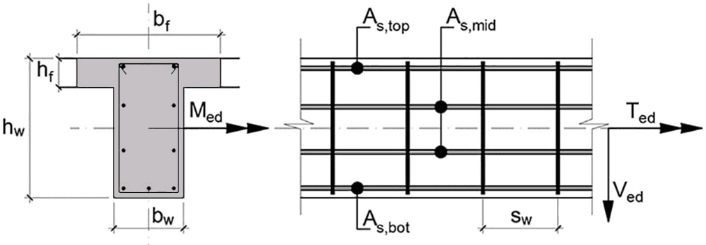
bw = 250 mm, hw = 500 mm
bf = 1200 mm, hf = 120 mm
Shear link legs count - nw = 2
Bottom bars diameter: Φb = 20 mm
Top and middle bars diameter: Φt = 12 mm
Links diameter (closed and anchored): Φs = 8 mm
Concrete cover - cnom = 25 mm
Effective cross section depth
d = hw − cnom − Φs − Φb2 = 500 − 25 − 8 − 202 = 457 mm
Number of middle rows of bars - nef = 2
[EN 1992-1-1, § 9.2.3 (4)]
Distance between rows of bars is 138mm ≤ 350 mmThe number of middle rows of bars is sufficient.Torsional moment - TEd = 20 kN·m
Bending moment - MEd = 200 kN·m
Shear force - VEd = 120 kN
Concrete [EN 1992-1-1, Table 3.1]
Characteristic compressive cylinder strength - fck = 20 MPa,
Partial safety factors for concrete - γc = 1.5 , αcc = 0.85
Design compressive cylinder strength - fcd = αcc · fckγc = 0.85 · 201.5 = 11.33 MPa
Mean value of axial tensile strength - fctm = 0.3 · fck23 = 0.3 · 2023 = 2.21 MPa
Characteristic axial tensile strength - fctk,005 = 0.7 · fctm = 0.7 · 2.21 = 1.55 MPa
Design axial tensile strength - fctd = fctk,005γc = 1.551.5 = 1.03 MPa
Steel
Characteristic yield strength - fyk = 500 MPa
Partial safety factor for steel - γs = 1.15
Design yield strength - fyd = fykγs = 5001.15 = 434.78 MPa
Modulus of elasticity - Es = 200000 MPa
Factor for effective compression zone depth - λ = 0.8
Effective strength factor - η = 1
Ultimate compressive strain in concrete - εcu3 = 0.0035
Flange area - Af = ( bf − bw ) · hf = ( 1200 − 250 ) · 120 = 114000 mm²
Flange first moment of area - Sf = Af · (d − hf2) = 114000 · (457 − 1202) = 45258000 mm³
Bending moment for neutral line at bottom edge of flange
Mf = bf · hf · η · fcd · (d − hf2) · 10-6 = 1200 · 120 · 1 · 11.33 · (457 − 1202) · 10-6 = 647.9 kN·m
The neutral line is within the flange - design of rectangular section with bf = 1200 mm
Relative design bending moment - mEd = MEd · 106bf · d2 · η · fcd = 200 · 1061200 · 4572 · 1 · 11.33 = 0.0704
Compression zone depth - x = dλ · ( 1 − √ 1 − 2 · mEd ) = 4570.8 · ( 1 − √ 1 − 2 · 0.0704 ) = 41.75 mm
Lever arm of internal forces - z = d − 0.5 · λ · x = 457 − 0.5 · 0.8 · 41.75 = 440.3 mm
Required tensile reinforcement area - As1 = MEd · 106z · fyd = 200 · 106440.3 · 434.78 = 1044.74 mm²
Reinforcement ratio - ρ1 = As1bw · d = 1044.74250 · 457 = 0.00914
[EN 1992-1-1, § 9.2.1.1]
Minimum tensile reinforcement ratio
ρmin = max(0.26 · fctmfyk; 0.0013) = max(0.26 · 2.21500; 0.0013) = 0.0013
Minimum area of tensile reinforcement - As,min = ρmin · bw · d = 0.0013 · 250 · 457 = 148.53 mm²
[EN 1992-1-1, § 6.2.2 and 6.3.2]
Bearing capacity without shear reinforcement
k = min(1 + 200d; 2) = min(1 + 200457; 2) = 1.66
CRd_c = 0.18γc = 0.181.5 = 0.12
ρL = min ( max ( ρmin; ρ1 ) ; 0.02 ) = min ( max ( 0.0013; 0.00914 ) ; 0.02 ) = 0.00914
νmin = 0.035 · k32 · √ fck = 0.035 · 1.6632 · √ 20 = 0.335
VRd,c_ = CRd_c · k · ( 100 · ρL · fck ) 13 · bw · d · 10-3 = 0.12 · 1.66 · ( 100 · 0.00914 · 20 ) 13 · 250 · 457 · 10-3 = 60.02 kN
VRd,c,min = νmin · bw · d · 10-3 = 0.335 · 250 · 457 · 10-3 = 38.3 kN
VRd,c = max ( VRd,c,min; VRd,c_ ) = max ( 38.3; 60.02 ) = 60.02 kN
Effective wall thickness
tef = max(bw · hw2 · ( bw + hw ) ; 2 · cnom) = max(250 · 5002 · ( 250 + 500 ) ; 2 · 25) = 83.33 mm
Total area of the cross section within the outer perimeter
Ak = ( bw − tef ) · ( hw − tef ) = ( 250 − 83.33 ) · ( 500 − 83.33 ) = 69444.4 mm²
Outer perimeter of the cross section
uk = 2 · ( bw + hw − 2 · tef ) = 2 · ( 250 + 500 − 2 · 83.33 ) = 1166.67 mm
Section subjected to pure torsion
TRd,c = 2 · Ak · tef · fctd · 10-6 = 2 · 69444.4 · 83.33 · 1.03 · 10-6 = 11.94 kN·m
[EN 1992-1-1, § 6.3.2 (5)]
TEdTRd,c + VEdVRd,c = 2011.94 + 12060.02 = 3.67 > 1 = 1
Shear reinforcement is required!
Bearing capacity with shear reinforcement
Lever arm of internal forces - z = 0.9 · d = 0.9 · 457 = 411.3 mm
αcw = 1 (when axial force NEd = 0)
[EN 1992-1-1, §6.2.2 (5)]
ν1 = 0.6 · (1 − fck250) = 0.6 · (1 − 20250) = 0.552
[(6.9) and (6.30) from EN 1992-1-1]
Maximum capacity for shear and torsion (θ = 45°)
VRd,max,45 = αcw · bw · z · ν1 · fcd2 · 10-3 = 1 · 250 · 411.3 · 0.552 · 11.332 · 10-3 = 321.64 kN
TRd,max,45 = ν1 · αcw · fcd · Ak · tef · 10-6 = 0.552 · 1 · 11.33 · 69444.4 · 83.33 · 10-6 = 36.2 kN·m
[(6.29) from EN 1992-1-1]
Maximum bearing capacity check
TEdTRd,max,45 + VEdVRd,max,45 = 2036.2 + 120321.64 = 0.926 ≤ 1 = 1 The design check is satisfied!
Angle between the concrete struts and the longitudinal reinforcement
θ = 0.5 · asin(TEdTRd,max,45 + VEdVRd,max,45) = 0.5 · asin(2036.2 + 120321.64) = 33.87 °
The angle is limited within 21,8° ≤ θ ≤ 45°
θ = max ( 21.8; min ( θ; 45 ) ) = max ( 21.8; min ( 33.87; 45 ) ) = 33.87 °
[(6.9) and (6.30) from EN 1992-1-1]
Bearing capacity check at θ = 33.87 °
VRd,max = αcw · bw · z · ν1 · fcd · cot ( θ ) 1 + cot ( θ ) 2 · 10-3 = 1 · 250 · 411.3 · 0.552 · 11.33 · cot ( 33.87 ) 1 + cot ( 33.87 ) 2 · 10-3 = 297.68 kN
TRd,max = 2 · ν1 · αcw · fcd · Ak · tef · sin ( θ ) · cos ( θ ) · 10-6 = 2 · 0.552 · 1 · 11.33 · 69444.4 · 83.33 · sin ( 33.87 ) · cos ( 33.87 ) · 10-6 = 33.51 kN·m
TEdTRd,max + VEdVRd,max = 2033.51 + 120297.68 = 1
(6.8) from EN 1992-1-1
Shear reinforcement area
Asw,V = VEd · 103z · fyd · cot ( θ ) = 120 · 103411.3 · 434.78 · cot ( 33.87 ) = 0.45 mm²/mm
Torsion reinforcement area
Asw,T = TEd · 106 · tan ( θ ) 2 · Ak · fyd = 20 · 106 · tan ( 33.87 ) 2 · 69444.4 · 434.78 = 0.222 mm²/mm
[EN 1992-1-1, § 9.2.2 (5)]
Minimum area of shear reinforcement
Asw,min = 0.08 · √ fckfyk · bw = 0.08 · √ 20500 · 250 = 0.179 mm²/mm
Total reinforcement required for shear and torsion
Asw = max ( Asw,V + Asw,T; Asw,min ) = max ( 0.45 + 0.222; 0.179 ) = 0.673 mm²/mm
Area of one leg - Asw,1 = π4 · Φs2 = 3.144 · 82 = 50.27 mm²
Calculation of shear link spacing
sw = nw · Asw,1Asw = 2 · 50.270.673 = 149.42 mm
Maximum shear link spacing
[EN 1992-1-1, §9.2.2]
sw,max,V = min ( 0.75 · d; 300 ) = min ( 0.75 · 457; 300 ) = 300 mm
[EN 1992-1-1, § 9.2.3]
sw,max,T = min(uk8; bw) = min(1166.678; 250) = 145.83 mm
Required longitudinal reinforcement area to resist torsion(6.28) from EN 1992-1-1
As,T = TEd · 106 · uk · cot ( θ ) 2 · Ak · fyd = 20 · 106 · 1166.67 · cot ( 33.87 ) 2 · 69444.4 · 434.78 = 575.6 mm²
Total longitudinal reinforcement for bending and torsion
Bottom reinforcement: As,b =1188.64mm² (4Ø20 bars)Top reinforcement: As,t =148.52mm² (2Ø12 bars)Middle reinforcement: As,m =287.8mm² (2Ø12 bars in 2 rows @ spacing 138 mm)Interaction Diagram of RC Section¶
N-M interaction diagram of a symmetrically reinforced rectangular section, generated by sweeping the neutral-axis depth from pure compression to pure tension and plotting the resulting axial force and bending moment.
'<small>According to <strong>Eurocode</strong>: EN 1992-1-1</small>
'<div style="max-width:180mm">
'<img class="side" style="width:150pt;" src="../../Images/structures/rc/design/column-design.png" alt="column-design.png">
'<h4>Cross section dimensions</h4>
'Width -'b = ?'mm, Height -'h = ?'mm
#post
'Cross section area -'A_c = b*h'mm²
#show
'<p><b>Reinforcement</b></p>
'Left -'A_s1 = ?'mm², Right -'A_s2 = A_s1'mm²
#post
'Reinforcement ratio -'ρ = (A_s1 + A_s2)/A_c
#show
'<p><b>Concrete cover</b> (to the center of the reinforcement)</p>
'Left -'d_1 = ?'mm, Right -'d_2 = d_1'mm
#post
'Effective cross section depth -'d = h - d_1'mm
#show
'<h4>Material properties</h4>
'<!--'PlotWidth = 250','PlotHeight = 125'-->
'<p><b>Concrete</b> [EN 1992-1-1, Table 3.1]</p>
'Characteristic compressive cylinder strength -'f_ck = ?'MPa
'Partial safety factors for concrete -'γ_c = 1.5','α_cc = ?
#post
'Mean value of cylinder compressive strength -'f_cm = f_ck + 8'MPa
'Design compressive cylinder strength -'f_cd = α_cc*f_ck/γ_c'MPa
'Ultimate compressive strain -'ε_cu2 = 0.0035'('ε_c2 = 0.002','n = 2')'
'Secant modulus of elasticity -'E_cm = 22*(f_cm/10)^0.3'GPa
#show
'<p><b>Steel</b></p>
'Characteristic yield strength -'f_yk = ?'MPa
#post
'Partial safety factor for steel -'γ_s = 1.15
'Design yield strength -'f_yd = f_yk/γ_s'MPa
'Modulus of elasticity -'E_s = 200'GPa
'<p><b>Strain-stress diagrams</b>, MPa:</p>
'<!--'PlotWidth = 250','PlotHeight = 125'-->
'<table><tr><td>
#hide
σ_c(ε) = f_cd*((1 - (1 - ε/ε_c2)^n)*(ε < ε_c2) + (ε ≥ ε_c2))
#post
$Plot{σ_c(ε/1000) @ ε = 0 : ε_cu2*1000}
'</td><td>
#hide
σ_s(ε) = max(-f_yd; min(ε*E_s*1000;f_yd))
#post
$Plot{σ_s(ε/1000) @ ε = -10 : 10}
'</td></tr></table>
'<h4>Interaction diagram</h4>
#hide
A_s_min = 0.00002*A_c
#if A_s1 < A_s_min
A_s1 = A_s_min
#end if
#if A_s2 < A_s_min
A_s2 = A_s_min
#end if
ε_s1,a(x) = ε_cu2*(d - x)/x
ε_s2,a(x) = ε_cu2*(d_2 - x)/x
N_c,a(x) = 17/21*x*b*f_cd/1000
N_s1,a(x) = σ_s(ε_s1,a(x))*A_s1/1000
N_s2,a(x) = σ_s(ε_s2,a(x))*A_s2/1000
N_Rd,a(x) = N_c,a(x) - N_s1,a(x) - N_s2,a(x)
z_c,a(x) = h/2 - 99/238*x
M_Rd,a(x) = (N_c,a(x)*z_c,a(x) + N_s1,a(x)*(h/2 - d_1) - N_s2,a(x)*(h/2 - d_2))/1000
x(ε) = h*ε_cu2/(ε_cu2 + ε)
h_c = h*ε_c2/ε_cu2
ε_s1,b(ε) = ε + (ε_c2 - ε)*d_1/h_c
ε_s2,b(ε) = ε + (ε_c2 - ε)*(h - d_2)/h_c
N_c,b(ε) = (h_c/6*(σ_c(ε) + 4*σ_c((ε + ε_c2)/2) + σ_c(ε_c2)) + (h - h_c)*f_cd)*b/1000
N_s1,b(ε) = σ_s(ε_s1,b(ε))*A_s1/1000
N_s2,b(ε) = σ_s(ε_s2,b(ε))*A_s2/1000
N_Rd,b(ε) = N_c,b(ε) + N_s1,b(ε) + N_s2,b(ε)
M_c0(ε) = (h_c^2/6*(2*σ_c((ε + ε_c2)/2) + σ_c(ε_c2)) + (h^2 - h_c^2)/2*f_cd)*b/1000
z_c,b(ε) = M_c0(ε)/N_c,b(ε) - h/2
M_Rd,b(ε) = (N_c,b(ε)*z_c,b(ε) - N_s1,b(ε)*(h/2 - d_1) + N_s2,b(ε)*(h/2 - d_2))/1000
N_Rd(ε) = N_Rd,a(x(ε))*(ε ≥ 0) + N_Rd,b(abs(ε))*(ε < 0)
M_Rd(ε) = M_Rd,a(x(ε))*(ε ≥ 0) + M_Rd,b(abs(ε))*(ε < 0)
ε_max = $Root{N_Rd(ε) - 1 @ ε = 0 : 2}
#if ε_max > 0.1
ε_max = 0.1
#end if
PlotWidth = 600
PlotHeight = 600
#post
'<p><i>N</i><sub>Rd</sub></p>
$Plot{M_Rd(ε)|N_Rd(ε) @ ε = ε_max : -ε_c2}
'<p style=float:right><i>M</i><sub>Rd</sub></p>
#show
'</div>
300 700 800 80 20 0.85 500
Width - b = 300 mm, Height - h = 700 mm
Cross section area - Ac = b · h = 300 · 700 = 210000 mm²
Reinforcement
Left - As1 = 800 mm², Right - As2 = As1 = 800 mm²
Reinforcement ratio - ρ = As1 + As2Ac = 800 + 800210000 = 0.00762
Concrete cover (to the center of the reinforcement)
Left - d1 = 80 mm, Right - d2 = d1 = 80 mm
Effective cross section depth - d = h − d1 = 700 − 80 = 620 mm
Concrete [EN 1992-1-1, Table 3.1]
Characteristic compressive cylinder strength - fck = 20 MPa
Partial safety factors for concrete - γc = 1.5 , αcc = 0.85
Mean value of cylinder compressive strength - fcm = fck + 8 = 20 + 8 = 28 MPa
Design compressive cylinder strength - fcd = αcc · fckγc = 0.85 · 201.5 = 11.33 MPa
Ultimate compressive strain - εcu2 = 0.0035 ( εc2 = 0.002 , n = 2 )
Secant modulus of elasticity - Ecm = 22 · (fcm10)0.3 = 22 · (2810)0.3 = 29.96 GPa
Steel
Characteristic yield strength - fyk = 500 MPa
Partial safety factor for steel - γs = 1.15
Design yield strength - fyd = fykγs = 5001.15 = 434.78 MPa
Modulus of elasticity - Es = 200 GPa
Strain-stress diagrams, MPa:
|
|
|
NRd

MRd
SLS Design of Beam with Rectangular Section¶
Serviceability checks for a rectangular beam: stress in the concrete and reinforcement, crack-width and long-term deflection, with the static scheme selected from a drop-down list (only in the Desktop version) of cantilevers and simply supported beams.
'<small>According to <strong>Eurocode</strong>: EN 1992-1-1</small>
'<div style="max-width:180mm">
'<h4>Static scheme</h4>
'<p id="type" class="flip_base" style="display:none">'type = ?'</p>
#pre
'<p><select data-target="type" class="flip_trigger">
'<option value="1">Cantilever with concentrated load</option>
'<option value="2">Cantilever with uniformly distributed load</option>
'<option value="3">Simply supported beam with concentrated load</option>
'<option value="0">Simply supported beam with uniformly distributed load</option>
'</select></p>
#hide
#if type ≡ 1
#show
'<img class="side flip flip_1" src="../../Images/structures/rc/design/deflection-cantilever-force.png" alt="deflection-cantilever-force.png" style="width:150pt;">
#post
'Cantilever with concentrated load
#hide
#else if type ≡ 2
#show
'<img class="side flip flip_2" src="../../Images/structures/rc/design/deflection-cantilever-uniform.png" alt="deflection-cantilever-uniform.png" style="width:150pt;">
#post
'Cantilever with uniformly distributed load
#hide
#else if type ≡ 3
#show
'<img class="side flip flip_3" src="../../Images/structures/rc/design/deflection-beam-force.png" alt="deflection-beam-force.png" style="width:150pt;">
#post
'Simply supported beam with concentrated load
#hide
#else if type ≡ 0
#show
'<img class="side flip flip_0" src="../../Images/structures/rc/design/deflection-beam-uniform.png" alt="deflection-beam-uniform.png" style="width:150pt;">
#post
'Simply supported beam with uniformly distributed load
#hide
#end if
#show
'Beam length -'L = ?'m
'Exposure class:
'<p id="w_max" style="display:none">'w_max = ?'</p>
#pre
'<p><select data-target="w_max">
'<option value="0.4">X0 or XC1</option>
'<option value="0.3">XC2, XC3, XC4, XD1, XD2, XS2 or XS3</option>
'</select></p>
#post
#if w_max ≡ 0.4
'X0 or XC1
#else
'XC2, XC3, XC4, XD1, XD2, XS2 or XS3
#end if
#show
''
'<h4>Bending moments</h4>
'Characteristic combination (<i>g</i> + <i>q</i>) -'M_k = ?'kNm
'Quasi-permanent combination (<i>g</i> + <i>ψ</i><sub>2</sub><i>q</i>) -'M_qp = ?'kNm
'
'<img class="side" src="../../Images/structures/rc/design/beam-section.png" alt="beam-section.png" style="width:120pt;">
'<h4>Cross section dimensions</h4>
'Width -'b = ?'mm, Height -'h = ?'mm
'Concrete cover -'c = ?'mm (to bars surface)
'<p><b>Tension reinforcement</b></p>
'Bar count -'n_1 = ?'with diameter -'Φ_1 = ?'mm
#post
'Reinforcement area -'A_s1 = n_1*π*Φ_1^2/4'mm²
#show
'Concrete cover to the center of reinforcement -'d_1 = ?'mm
#post
'Effective cross section depth -'d = h - d_1'mm
#show
'Spacing between bar centers -'s = ?'mm
'<p><b>Compression reinforcement</b></p>
'Bar count -'n_2 = ?'with diameter -'Φ_2 = ?'mm
#post
'Reinforcement area -'A_s2 = n_2*π*Φ_2^2/4'mm²
#show
'Concrete cover to the center of reinforcement -'d_2 = ?'mm
'
'<h4>Material properties</h4>
'<p><b>Concrete</b> [EN 1992-1-1, Table 3.1]</p>
'Characteristic compressive cylinder strength -'f_ck = ?'MPa
#post
'Mean value of cylinder compressive strength -'f_cm = f_ck + 8'MPa
'Mean value of axial tensile strength -'f_ctm = 0.30*f_ck^(2/3)'MPa
'Secant modulus of elasticity -'E_cm = 22*(f_cm/10)^0.3'GPa
#show
'<p><b>Steel</b></p>
'Characteristic yield strength -'f_yk = ?'MPa
#post
'Modulus of elasticity -'E_s = 200'GPa
'Ratio of steel to conrete moduli of elasticity -'α = E_s/E_cm
'
'<div class="fold">
#show
'<h4>Concrete creep and shrinkage</h4>
'<p class = "ref">[EN 1992-1-1 B.1(1)]</p>
'<p><b>Creep</b></p>
'Relative humidity of the environment -'RH = ?'%
#post
'Perimeter of cross section in contact with the atmosphere
u = 2*(b + h)'mm
'Cross section area -'A_c = b*h'mm²
'Notional size of the cross section
'<p class = "ref">(eq. B.6)</p>
h_0 = 2*A_c/u'mm
'Relative humidity factor
#if f_cm ≤ 35
'<p class = "ref">(eq. B.3a)</p>
φ_RH = (1 + (1 - RH/100)/(0.1*h_0^0.333))
#else
'<p class = "ref">(eq. B.8c)</p>
α_1 = (35/f_cm)^0.7','α_2 = (35/f_cm)^0.2
'<p class = "ref">(eq. B.3b)</p>
φ_RH = (1 + (1 - RH/100)/(0.1*h_0^0.333)*α_1)*α_2
#end if
'Concrete strength factor
'<p class = "ref">(eq. B.4)</p>
β_f_cm = 16.8/sqr(f_cm)
'Concrete age at the moment of loading -'t_0 = 28'дни
'Concrete age factor
'<p class = "ref">(eq. B.5)</p>
β_t0 = 1/(0.1 + t_0^0.20)
'Notional creep coefficient
'<p class = "ref">(eq. B.2)</p>
φ_8_t0 = φ_RH*β_f_cm*β_t0
'Effective concrete modulus of elasticity
'<p class = "ref">[EN 1992-1-1 §7.4.3(5)]</p>
E_c_eff = E_cm/(1 + φ_8_t0)'GPa
'Effective ratio of modules of elasticity
'<p class = "ref">[EN 1992-1-1 §7.4.3(6)]</p>
α_e = E_s/E_c_eff
'<p class = "ref">[EN 1992-1-1 B.2(1)]</p>
'<p><b>Shrinkage</b></p>
'Coefficient depending on the notional size
#if h_0 ≤ 100
k_h = 1.00
#else if h_0 ≤ 200
k_h = 1.00 - 0.0015*(h_0 - 100)
#else if h_0 ≤ 300
k_h = 0.85 - 0.001*(h_0 - 200)
#else if h_0 ≤ 500
k_h = 0.75 - 0.00025*(h_0 - 300)
#else
k_h = 0.70
#end if
α_ds1 = 4'- for cement Class N
α_ds2 = 0.12'- for cement Class N
'<p class = "ref">(eq. B.12)</p>
β_RH = 1.55*(1 - (RH/100)^3)
'Basic drying shrinkage strain
'<p class = "ref">(eq. B.11)</p>
ε_cd0 = 0.85*(220 + 110*α_ds1)*e^(-α_ds2*f_cm/10)*10^-6*β_RH
'<p class = "ref">[EN 1992-1-1 §3.1.4(6)]</p>
'Drying shrinkage strain in time
'<p class = "ref">(eq. 3.9)</p>
ε_cd = k_h*ε_cd0
'Autogenous shrinkage strain
'<p class = "ref">(eq. 3.11)</p>
ε_ca = 2.5*(f_ck - 10)*10^(-6)
'Total shrinkage strain
'<p class = "ref">(eq. 3.8)</p>
ε_cs = ε_cd + ε_ca
'</div>
'
'<div class="fold">
'<h4>Cross section properties</h4>
'Total reinforcement area -'A_s = A_s1 + A_s2'mm²
'Concrete area -'A_c = b*h'mm²
'Effective section area
A_red = A_c + α_e*A_s'mm²
'Section modulus about the bottom edge
S_c = b*h^2/2'mm<sup>3</sup>
'Effective section modulus about the bottom edge
S_red = S_c + α_e*(A_s1*d_1 + A_s2*(h - d_2))'mm<sup>3</sup>
'Effective depth of cross section center
z_c = S_red/A_red'mm
'Second moment of area of the concrete section
I_c = b*h^3/12 + A_c*(z_c - S_c/A_c)^2'mm<sup>4</sup>
'Second moment of area for uncracked section
I_red = I_c + α_e*(A_s1*(z_c - d_1)^2 + A_s2*(h - z_c - d_2)^2)'mm<sup>4</sup>
'Depth of neutral axis for cracked section
x = (sqr(A_s^2 + 2*b*(d*A_s1 + d_2*A_s2)/α_e) - A_s)*α_e/b'mm
'Second moment of area for cracked section
I_red_II = b*x^3/3 + α_e*(A_s1*(d - x)^2 + A_s2*(x - d_2)^2)'mm<sup>4</sup>
'</div>
'
'<div class="fold">
'<h4>Control of concrete stress</h4>
'<p><b>Characteristic combination</b></p>
'Stress at the bottom edge of the section
σ_ct = M_k*10^6/I_red*z_c'MPa
'Check for crack opening
#if σ_ct ≤ f_ctm
σ_ct'MPa &lе;'f_ctm'MPa - section is uncracked
'Concrete stress (uncracked section)
σ_c = M_k*10^6/I_red*(h - z_c)'MPa
'Reinforcement stress (uncracked section)
σ_s1 = α_e*M_k*10^6/I_red*(z_c - d_1)'MPa
σ_s2 = -α_e*M_k*10^6/I_red*(h - z_c - d_2)'MPa
#else
σ_ct'MPa >'f_ctm'MPa - section is cracked
'Concrete stress (cracked section)
σ_c = M_k*10^6/I_red_II*x'MPa
'Reinforcement stress (cracked section)
σ_s1 = α_e*M_k*10^6/I_red_II*(d - x)'MPa
σ_s2 = -α_e*M_k*10^6/I_red_II*(x - d_2)'MPa
#end if
'<p><b>Stress limitation</b></p>
'<p class = "ref">[EN 1992-1-1 §7.2(2)]</p>
'Concrete stress,'k_1 = 0.60
#if σ_c > k_1*f_ck
σ_c'MPa >'k_1*f_ck'MPa - <span class="err">The condition is NOT satisfied!</span>
#else
σ_c'MPa ≤'k_1*f_ck'MPa - The condition is satisfied!
#end if
'<p class = "ref">[EN 1992-1-1 §7.2(5)]</p>
'Reinforcement stress,'k_3 = 0.80
#if σ_s1 > k_3*f_yk
σ_s1'MPa >'k_3*f_yk'MPa - <span class="err">The condition is NOT satisfied!</span>
#else
σ_s1'MPa ≤'k_3*f_yk'MPa - The condition is satisfied!
#end if
'<p><b>Quasi-permanent combination</b></p>
#if σ_ct ≤ f_ctm
'Concrete stress for uncracked section
σ_c = M_qp*10^6/I_red*(h - z_c)'MPa
#else
'Concrete stress for cracked section
σ_c = M_qp*10^6/I_red_II*x'MPa
#end if
'<p class = "ref">[EN 1992-1-1 §7.2(3)]</p>
'Stress limitation,'k_2 = 0.45
#if σ_c > k_2*f_ck
σ_c'MPa >'k_2*f_ck'MPa - <span class="err">The condition is NOT satisfied!</span>
'<p class = "ref">[EN 1992-1-1 §3.1.4(4)]</p>
'Non-linear creep must be considered!
k_σ = σ_c/f_ck
'Non-linear notional creep coefficient
φ_k_8_t0 = φ_8_t0*e^(1.5*(k_σ - 0.45))
'Effective concrete modulus of elasticity
E_c_eff = E_cm/(1 + φ_k_8_t0)'MPa
#else
σ_c'MPa ≤'k_2*f_ck'MPa - The condition is satisfied!
'Non-linear creep is NOT calculated!
#end if
'</div>
'
'<div class="fold">
'<h4>Control of cracks</h4>
'<p class = "ref">[EN 1992-1-1 §7.3.2(2)]</p>
'<p><b>Minimum reinforcement area</b></p>
'Allowable reinforcement stress -'σ_s = f_yk'MPa
'Approximate value of axial tensile strength -'f_ct_eff = f_ctm'MPa
'Area of tensile zone before opening of first crack
A_ct = b*z_c'mm²
#if h ≤ 300
k = 1'- for h ≤ 300 mm
#else if h ≥ 800
k = 0.65'- for h ≥ 800 mm
#else
k = 1 - 0.35*(h - 300)/500'- for 300 mm < h < 800 mm
#end if
k_c = 0.4
#if h ≤ 1000
h_1 = h'- for h ≤ 1000 mm
#else
h_1 = 1000'- for h > 1000 mm
#end if
'Minimum reinforcement
A_s_min = k_c*k*f_ct_eff*A_ct/σ_s'mm²
#if A_s1 < A_s_min
A_s1'mm² <'A_s_min'mm² - <span class="err">The condition is NOT satisfied!</span>
#else
A_s1'mm² ≥'A_s_min'mm² - The condition is satisfied!
#end if
'<p><b>Calculation of crack widths</b></p>
'<p class = "ref">[EN 1992-1-1 §7.3.2(3)]</p>
'Depth of the effective area
h_c_eff = min(2.5*(h - d);min(h - x/3;h/2))'mm
'Concrete effective area within tensile zone
A_c_eff = b*h_c_eff'mm²
ρ_p_eff = A_s1/A_c_eff
'<p class = "ref">[EN 1992-1-1 §7.3.4(3)]</p>
#if s > 5*(c + Φ_1/2)
'For's'mm >'5*(c + Φ_1/2)'mm:
'Maximum final crack spacing -'s_r_max = 1.3*(h - x)'mm
#else
'For's'mm ≤'5*(c + Φ_1/2)'mm:
k_1 = 0.8'- for high bond bars
k_2 = 0.5'- for bending
k_3 = 3.4','k_4 = 0.425
'Maximum final crack spacing
s_r_max = k_3*c + k_1*k_2*k_4*Φ_1/ρ_p_eff'mm
#end if
'The check is performed for quasi-permanent combination
'Reinforcement stress
σ_s = α_e*M_qp*10^6/I_red_II*(d - x)'MPa
'Long-term load factor -'k_t = 0.4
'<p class = "ref">[EN 1992-1-1 §7.3.4(2)]</p>
'Difference between mean values of concrete and reinforcement strains
'<p><i>ε</i><sub>sm</sub> - <i>ε</i><sub>cm</sub> ='Δε = max((σ_s - k_t*f_ct_eff/ρ_p_eff*(1 + α*ρ_p_eff));0.6*σ_s)/(E_s*10^3)'</p>
'<p class = "ref">[EN 1992-1-1 §7.3.4(1)]</p>
'Crack widths
w_k = s_r_max*Δε'mm
'<p class = "ref">[EN 1992-1-1 §7.3.1(5)]</p>
'Limiting crack width value
'<p class = "ref">[EN 1992-1-1, Table NA.4]</p>
#if w_max ≡ 0.4
w_max'mm - for exposure classes X0, XC1
#else
w_max'mm - for exposure classes XC2, XC3, XC4, XD1, XD2, XS2, XS3
#end if
'Crack width limitation
'</div>
#if w_k > w_max
w_k'mm >'w_max'mm - <span class="err">The condition is NOT satisfied!</span>
#else
w_k'mm ≤'w_max'mm - The condition is satisfied!
#end if
'
'<div class="fold">
'<h4>Control of deflections</h4>
'Crack opening moment
#if σ_ct ≤ f_ctm
'Distribution coefficient
'<p class = "ref">[EN 1992-1-1 §7.4.3(3)]</p>
ζ = 0'- for uncracked section
#else
M_cr = f_ctm*I_red/z_c*10^-6'kNm
'Coefficient for duration of loads
β = 0.5'- for long-term loads
'<p class = "ref">[EN 1992-1-1 §7.4.3(3)]</p>
'Distribution coefficient
ζ = 1 - β*(M_cr/M_qp)^2'- for cracked section
#end if
'<p><b>Calculation of curvature</b></p>
'First moment of reinforcement area about centroid of uncracked section
S = A_s1*(z_c - d_1) - A_s2*(h - z_c - d_2)'mm<sup>3</sup>
'Curvature due to shrinkage of uncracked section
'<p class = "ref">[EN 1992-1-1 §7.4.3(6)]</p>
θ_cs_I = ε_cs*α_e*S/I_red
'Curvature of uncracked section
θ_I = M_qp/(E_c_eff*I_red)*10^3 + θ_cs_I
'First moment of reinforcement area about centroid of cracked section
S = A_s1*(d - x) - A_s2*(x - d_2)'mm<sup>3</sup>
'Curvature due to shrinkage of cracked section
'<p class = "ref">[EN 1992-1-1 §7.4.3(6)]</p>
θ_cs_II = ε_cs*α_e*S/I_red_II
'Curvature of cracked section
θ_II = M_qp/(E_c_eff*I_red_II)*10^3 + θ_cs_II
'Total curvature
'<p class = "ref">[EN 1992-1-1 §7.4.3(3)]</p>
θ = ζ*θ_II + (1 - ζ)*θ_I
'Factor considering the static scheme
#if type ≡ 1
k = 1/3'- for cantilever with concentrated load
#else if type ≡ 2
k = 1/4'- for cantilever with uniformly distributed load
#else if type ≡ 3
k = 1/12'- for simply supported beam with concentrated load
#else if type ≡ 0
k = 5/48'- for simply supported beam with uniformly distributed load
#end if
'Deflection due to quasi-permanent combination -'δ = k*θ*L^2*10^6'mm
'<p class = "ref">[EN 1992-1-1 §7.4.1(4)]</p>
#if (type ≡ 1) + (type ≡ 2)
'Maximum deflection -'δ_max = L*10^3/125'mm
#else
'Maximum deflection -'δ_max = L*10^3/250'mm
#end if
'Deflection check:
'</div>
#if δ > δ_max
δ'mm >'δ_max'mm - <span class="err">The condition is NOT satisfied!</span>
#else
δ'mm ≤'δ_max'mm - The condition is satisfied!
#end if
#show
'</div>
#pre
'<script>if(window.jQuery){$(".flip_trigger").change(function(){$(".flip").hide();$(".flip_"+$(this).val()).show();});$(".flip").hide();$(".flip_"+$(".flip_base input").val()).show();}</script>
0 7 0.4 200 150 300 650 30 4 20 45 74 2 14 45 20 500 50
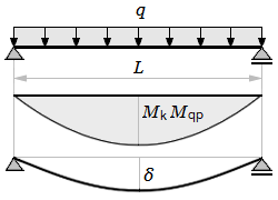
Simply supported beam with uniformly distributed load
Beam length - L = 7 m
Exposure class:
X0 or XC1
Characteristic combination (g + q) - Mk = 200 kNm
Quasi-permanent combination (g + ψ2q) - Mqp = 150 kNm
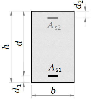
Width - b = 300 mm, Height - h = 650 mm
Concrete cover - c = 30 mm (to bars surface)
Tension reinforcement
Bar count - n1 = 4 with diameter - Φ1 = 20 mm
Reinforcement area - As1 = n1 · π · Φ124 = 4 · 3.14 · 2024 = 1256.64 mm²
Concrete cover to the center of reinforcement - d1 = 45 mm
Effective cross section depth - d = h − d1 = 650 − 45 = 605 mm
Spacing between bar centers - s = 74 mm
Compression reinforcement
Bar count - n2 = 2 with diameter - Φ2 = 14 mm
Reinforcement area - As2 = n2 · π · Φ224 = 2 · 3.14 · 1424 = 307.88 mm²
Concrete cover to the center of reinforcement - d2 = 45 mm
Concrete [EN 1992-1-1, Table 3.1]
Characteristic compressive cylinder strength - fck = 20 MPa
Mean value of cylinder compressive strength - fcm = fck + 8 = 20 + 8 = 28 MPa
Mean value of axial tensile strength - fctm = 0.3 · fck23 = 0.3 · 2023 = 2.21 MPa
Secant modulus of elasticity - Ecm = 22 · (fcm10)0.3 = 22 · (2810)0.3 = 29.96 GPa
Steel
Characteristic yield strength - fyk = 500 MPa
Modulus of elasticity - Es = 200 GPa
Ratio of steel to conrete moduli of elasticity - α = EsEcm = 20029.96 = 6.68
[EN 1992-1-1 B.1(1)]
Creep
Relative humidity of the environment - RH = 50 %
Perimeter of cross section in contact with the atmosphere
u = 2 · ( b + h ) = 2 · ( 300 + 650 ) = 1900 mm
Cross section area - Ac = b · h = 300 · 650 = 195000 mm²
Notional size of the cross section
(eq. B.6)
h0 = 2 · Acu = 2 · 1950001900 = 205.26 mm
Relative humidity factor
(eq. B.3a)
φRH = 1 + 1 − RH1000.1 · h00.333 = 1 + 1 − 501000.1 · 205.260.333 = 1.85
Concrete strength factor
(eq. B.4)
βf_cm = 16.8 √ fcm = 16.8 √ 28 = 3.17
Concrete age at the moment of loading - t0 = 28 дни
Concrete age factor
(eq. B.5)
βt0 = 10.1 + t00.2 = 10.1 + 280.2 = 0.488
Notional creep coefficient
(eq. B.2)
φ8_t0 = φRH · βf_cm · βt0 = 1.85 · 3.17 · 0.488 = 2.87
Effective concrete modulus of elasticity
[EN 1992-1-1 §7.4.3(5)]
Ec_eff = Ecm1 + φ8_t0 = 29.961 + 2.87 = 7.75 GPa
Effective ratio of modules of elasticity
[EN 1992-1-1 §7.4.3(6)]
αe = EsEc_eff = 2007.75 = 25.82
[EN 1992-1-1 B.2(1)]
Shrinkage
Coefficient depending on the notional size
kh = 0.85 − 0.001 · ( h0 − 200 ) = 0.85 − 0.001 · ( 205.26 − 200 ) = 0.845
αds1 = 4 - for cement Class N
αds2 = 0.12 - for cement Class N
(eq. B.12)
βRH = 1.55 · (1 − (RH100)3) = 1.55 · (1 − (50100)3) = 1.36
Basic drying shrinkage strain
(eq. B.11)
εcd0 = 0.85 · ( 220 + 110 · αds1 ) · e-αds2 · fcm10 · 10-6 · βRH = 0.85 · ( 220 + 110 · 4 ) · 2.72-0.12 · 2810 · 10-6 · 1.36 = 0.000544
[EN 1992-1-1 §3.1.4(6)]
Drying shrinkage strain in time
(eq. 3.9)
εcd = kh · εcd0 = 0.845 · 0.000544 = 0.000459
Autogenous shrinkage strain
(eq. 3.11)
εca = 2.5 · ( fck − 10 ) · 10-6 = 2.5 · ( 20 − 10 ) · 10-6 = 2.5×10⁻⁵
Total shrinkage strain
(eq. 3.8)
εcs = εcd + εca = 0.000459 + 2.5×10-5 = 0.000484
Total reinforcement area - As = As1 + As2 = 1256.64 + 307.88 = 1564.51 mm²
Concrete area - Ac = b · h = 300 · 650 = 195000 mm²
Effective section area
Ared = Ac + αe · As = 195000 + 25.82 · 1564.51 = 235390 mm²
Section modulus about the bottom edge
Sc = b · h22 = 300 · 65022 = 63375000 mm3
Effective section modulus about the bottom edge
Sred = Sc + αe · ( As1 · d1 + As2 · ( h − d2 ) ) = 63375000 + 25.82 · ( 1256.64 · 45 + 307.88 · ( 650 − 45 ) ) = 69643628 mm3
Effective depth of cross section center
zc = SredAred = 69643628235390 = 295.86 mm
Second moment of area of the concrete section
Ic = b · h312 + Ac · (zc − ScAc)2 = 300 · 650312 + 195000 · (295.86 − 63375000195000)2 = 7031158285 mm4
Second moment of area for uncracked section
Ired = Ic + αe · ( As1 · ( zc − d1 ) 2 + As2 · ( h − zc − d2 ) 2 ) = 7031158285 + 25.82 · ( 1256.64 · ( 295.86 − 45 ) 2 + 307.88 · ( 650 − 295.86 − 45 ) 2 ) = 9832414931 mm4
Depth of neutral axis for cracked section
x = ( As2 + 2 · b · ( d · As1 + d2 · As2 ) αe − As) · αeb = ( 1564.512 + 2 · 300 · ( 605 · 1256.64 + 45 · 307.88 ) 25.82 − 1564.51) · 25.82300 = 254.42 mm
Second moment of area for cracked section
Ired_II = b · x33 + αe · ( As1 · ( d − x ) 2 + As2 · ( x − d2 ) 2 ) = 300 · 254.4233 + 25.82 · ( 1256.64 · ( 605 − 254.42 ) 2 + 307.88 · ( 254.42 − 45 ) 2 ) = 5982777984 mm4
Characteristic combination
Stress at the bottom edge of the section
σct = Mk · 106Ired · zc = 200 · 1069832414931 · 295.86 = 6.02 MPa
Check for crack opening
σct = 6.02 MPa > fctm = 2.21 MPa - section is cracked
Concrete stress (cracked section)
σc = Mk · 106Ired_II · x = 200 · 1065982777984 · 254.42 = 8.5 MPa
Reinforcement stress (cracked section)
σs1 = αe · Mk · 106Ired_II · ( d − x ) = 25.82 · 200 · 1065982777984 · ( 605 − 254.42 ) = 302.56 MPa
σs2 = -αe · Mk · 106Ired_II · ( x − d2 ) = -25.82 · 200 · 1065982777984 · ( 254.42 − 45 ) = -180.73 MPa
Stress limitation
[EN 1992-1-1 §7.2(2)]
Concrete stress, k1 = 0.6
σc = 8.5 MPa ≤ k1 · fck = 0.6 · 20 = 12 MPa - The condition is satisfied!
[EN 1992-1-1 §7.2(5)]
Reinforcement stress, k3 = 0.8
σs1 = 302.56 MPa ≤ k3 · fyk = 0.8 · 500 = 400 MPa - The condition is satisfied!
Quasi-permanent combination
Concrete stress for cracked section
σc = Mqp · 106Ired_II · x = 150 · 1065982777984 · 254.42 = 6.38 MPa
[EN 1992-1-1 §7.2(3)]
Stress limitation, k2 = 0.45
σc = 6.38 MPa ≤ k2 · fck = 0.45 · 20 = 9 MPa - The condition is satisfied!
Non-linear creep is NOT calculated!
[EN 1992-1-1 §7.3.2(2)]
Minimum reinforcement area
Allowable reinforcement stress - σs = fyk = 500 MPa
Approximate value of axial tensile strength - fct_eff = fctm = 2.21 MPa
Area of tensile zone before opening of first crack
Act = b · zc = 300 · 295.86 = 88759.3 mm²
k = 1 − 0.35 · ( h − 300 ) 500 = 1 − 0.35 · ( 650 − 300 ) 500 = 0.755 - for 300 mm < h < 800 mm
kc = 0.4
h1 = h = 650 - for h ≤ 1000 mm
Minimum reinforcement
As_min = kc · k · fct_eff · Actσs = 0.4 · 0.755 · 2.21 · 88759.3500 = 118.5 mm²
As1 = 1256.64 mm² ≥ As_min = 118.5 mm² - The condition is satisfied!
Calculation of crack widths
[EN 1992-1-1 §7.3.2(3)]
Depth of the effective area
hc_eff = min(2.5 · ( h − d ) ; min(h − x3; h2)) = min(2.5 · ( 650 − 605 ) ; min(650 − 254.423; 6502)) = 112.5 mm
Concrete effective area within tensile zone
Ac_eff = b · hc_eff = 300 · 112.5 = 33750 mm²
ρp_eff = As1Ac_eff = 1256.6433750 = 0.0372
[EN 1992-1-1 §7.3.4(3)]
For s = 74 mm ≤ 5 · (c + Φ12) = 5 · (30 + 202) = 200 mm:
k1 = 0.8 - for high bond bars
k2 = 0.5 - for bending
k3 = 3.4 , k4 = 0.425
Maximum final crack spacing
sr_max = k3 · c + k1 · k2 · k4 · Φ1ρp_eff = 3.4 · 30 + 0.8 · 0.5 · 0.425 · 200.0372 = 193.32 mm
The check is performed for quasi-permanent combination
Reinforcement stress
σs = αe · Mqp · 106Ired_II · ( d − x ) = 25.82 · 150 · 1065982777984 · ( 605 − 254.42 ) = 226.92 MPa
Long-term load factor - kt = 0.4
[EN 1992-1-1 §7.3.4(2)]
Difference between mean values of concrete and reinforcement strains
εsm - εcm = Δε = max(σs − kt · fct_effρp_eff · ( 1 + α · ρp_eff ) ; 0.6 · σs)Es · 103 = max(226.92 − 0.4 · 2.210.0372 · ( 1 + 6.68 · 0.0372 ) ; 0.6 · 226.92)200 · 103 = 0.000986
[EN 1992-1-1 §7.3.4(1)]
Crack widths
wk = sr_max · Δε = 193.32 · 0.000986 = 0.191 mm
[EN 1992-1-1 §7.3.1(5)]
Limiting crack width value
[EN 1992-1-1, Table NA.4]
wmax = 0.4 mm - for exposure classes X0, XC1
Crack width limitation
wk = 0.191 mm ≤ wmax = 0.4 mm - The condition is satisfied!
Crack opening moment
Mcr = fctm · Iredzc · 10-6 = 2.21 · 9832414931295.86 · 10-6 = 73.46 kNm
Coefficient for duration of loads
β = 0.5 - for long-term loads
[EN 1992-1-1 §7.4.3(3)]
Distribution coefficient
ζ = 1 − β · (McrMqp)2 = 1 − 0.5 · (73.46150)2 = 0.88 - for cracked section
Calculation of curvature
First moment of reinforcement area about centroid of uncracked section
S = As1 · ( zc − d1 ) − As2 · ( h − zc − d2 ) = 1256.64 · ( 295.86 − 45 ) − 307.88 · ( 650 − 295.86 − 45 ) = 220070 mm3
Curvature due to shrinkage of uncracked section
[EN 1992-1-1 §7.4.3(6)]
θcs_I = εcs · αe · SIred = 0.000484 · 25.82 · 2200709832414931 = 2.8×10⁻⁷
Curvature of uncracked section
θI = MqpEc_eff · Ired · 103 + θcs_I = 1507.75 · 9832414931 · 103 + 2.8×10-7 = 2.25×10⁻⁶
First moment of reinforcement area about centroid of cracked section
S = As1 · ( d − x ) − As2 · ( x − d2 ) = 1256.64 · ( 605 − 254.42 ) − 307.88 · ( 254.42 − 45 ) = 376082 mm3
Curvature due to shrinkage of cracked section
[EN 1992-1-1 §7.4.3(6)]
θcs_II = εcs · αe · SIred_II = 0.000484 · 25.82 · 3760825982777984 = 7.86×10⁻⁷
Curvature of cracked section
θII = MqpEc_eff · Ired_II · 103 + θcs_II = 1507.75 · 5982777984 · 103 + 7.86×10-7 = 4.02×10⁻⁶
Total curvature
[EN 1992-1-1 §7.4.3(3)]
θ = ζ · θII + ( 1 − ζ ) · θI = 0.88 · 4.02×10-6 + ( 1 − 0.88 ) · 2.25×10-6 = 3.81×10⁻⁶
Factor considering the static scheme
k = 548 = 0.104 - for simply supported beam with uniformly distributed load
Deflection due to quasi-permanent combination - δ = k · θ · L2 · 106 = 0.104 · 3.81×10-6 · 72 · 106 = 19.45 mm
[EN 1992-1-1 §7.4.1(4)]
Maximum deflection - δmax = L · 103250 = 7 · 103250 = 28 mm
Deflection check:
δ = 19.45 mm ≤ δmax = 28 mm - The condition is satisfied!
SLS Design of Beam with Tee Section¶
Serviceability checks for a T-beam: same stress, crack-width and deflection verifications as the rectangular variant, with the cracked-section second moment of area derived for both flange-in-compression and web-in-compression cases.
'<small>According to <strong>Eurocode</strong>: EN 1992-1-1</small>
'<div style="max-width:180mm">
'<h4>Static scheme</h4>
'<p id="type" class="flip_base" style="display:none">'type = ?'</p>
#pre
'<p><select data-target="type" class="flip_trigger">
'<option value="1">Cantilever with concentrated load</option>
'<option value="2">Cantilever with uniformly distributed load</option>
'<option value="3">Simply supported beam with concentrated load</option>
'<option value="0">Simply supported beam with uniformly distributed load</option>
'</select></p>
#hide
#if type ≡ 1
#show
'<img class="side flip flip_1" src="../../Images/structures/rc/design/deflection-cantilever-force.png" alt="deflection-cantilever-force.png" style="width:150pt;">
#post
'Cantilever with concentrated load
#hide
#else if type ≡ 2
#show
'<img class="side flip flip_2" src="../../Images/structures/rc/design/deflection-cantilever-uniform.png" alt="deflection-cantilever-uniform.png" style="width:150pt;">
#post
'Cantilever with uniformly distributed load
#hide
#else if type ≡ 3
#show
'<img class="side flip flip_3" src="../../Images/structures/rc/design/deflection-beam-force.png" alt="deflection-beam-force.png" style="width:150pt;">
#post
'Simply supported beam with concentrated load
#hide
#else if type ≡ 0
#show
'<img class="side flip flip_0" src="../../Images/structures/rc/design/deflection-beam-uniform.png" alt="deflection-beam-uniform.png" style="width:150pt;">
#post
'Simply supported beam with uniformly distributed load
#hide
#end if
#show
'Beam length -'L = ?'m
'Exposure class:
'<p id="w_max" style="display:none">'w_max = ?'</p>
#pre
'<p><select data-target="w_max">
'<option value="0.4">X0 or XC1</option>
'<option value="0.3">XC2, XC3, XC4, XD1, XD2, XS2 или XS3</option>
'</select></p>
#post
#if w_max ≡ 0.4
'X0 or XC1
#else
'XC2, XC3, XC4, XD1, XD2, XS2 или XS3
#end if
#show
'
'<h4>Bending moments</h4>
'Characteristic combination (<i>g</i> + <i>q</i>) -'M_k = ?'kNm
'Quasi-permanent combination (<i>g</i> + <i>ψ</i><sub>2</sub><i>q</i>) -'M_qp = ?'kNm
'
'<img class="side" src="../../Images/structures/rc/design/beam-tsection.png" alt="beam-tsection.png" style="width:150pt;">
'<h4>Cross section dimensions</h4>
'Stem:'b = ?'mm,'h = ?'mm
'Flange:'b_f = ?'mm,'h_f = ?'mm
'Concrete cover -'c = ?'mm (to bars surface)
'<p><b>Tension reinforcement</b></p>
'Bar count -'n_1 = ?'with diameter -'Φ_1 = ?'mm
#post
'Reinforcement area -'A_s1 = n_1*π*Φ_1^2/4'mm²
#show
'Concrete cover to the center of reinforcement -'d_1 = ?'mm
#post
'Effective cross section depth -'d = h - d_1'mm
#show
'Spacing between bar centers -'s = ?'mm
'<p><b>Compression reinforcement</b></p>
'Bar count -'n_2 = ?'with diameter -'Φ_2 = ?'mm
#post
'Reinforcement area -'A_s2 = n_2*π*Φ_2^2/4'mm²
#show
'Concrete cover to the center of reinforcement -'d_2 = ?'mm
'
'<h4>Material properties</h4>
'<p><b>Concrete</b> [EN 1992-1-1, Table 3.1]</p>
'Characteristic compressive cylinder strength -'f_ck = ?'MPa
#post
'Mean value of cylinder compressive strength -'f_cm = f_ck + 8'MPa
'Mean value of axial tensile strength -'f_ctm = 0.30*f_ck^(2/3)'MPa
'Secant modulus of elasticity -'E_cm = 22*(f_cm/10)^0.3'GPa
#show
'<p><b>Steel</b></p>
'Characteristic yield strength -'f_yk = ?'MPa
#post
'Modulus of elasticity -'E_s = 200'GPa
'Ratio of steel to concrete moduli of elasticity -'α = E_s/E_cm
'
'<div class="fold">
#show
'<h4>Concrete creep and shrinkage</h4>
'<p class = "ref">[EN 1992-1-1 B.1(1)]</p>
'<p><b>Creep</b></p>
'Relative humidity of the environment -'RH = ?'%
#post
'Perimeter of cross section in contact with the atmosphere
u = 2*(b + h)'mm
'Cross section area -'A_c = b*h'mm²
'Notional size of the cross section
'<p class = "ref">(eq. B.6)</p>
h_0 = 2*A_c/u'mm
'Relative humidity factor
#if f_cm ≤ 35
'<p class = "ref">(eq. B.3a)</p>
φ_RH = (1 + (1 - RH/100)/(0.1*h_0^0.333))
#else
'<p class = "ref">(eq. B.8c)</p>
α_1 = (35/f_cm)^0.7','α_2 = (35/f_cm)^0.2
'<p class = "ref">(eq. B.3b)</p>
φ_RH = (1 + (1 - RH/100)/(0.1*h_0^0.333)*α_1)*α_2
#end if
'Concrete strength factor
'<p class = "ref">(eq. B.4)</p>
β_f_cm = 16.8/sqr(f_cm)
'Concrete age at the moment of loading -'t_0 = 28'дни
'Concrete age factor
'<p class = "ref">(eq. B.5)</p>
β_t0 = 1/(0.1 + t_0^0.20)
'Notional creep coefficient
'<p class = "ref">(eq. B.2)</p>
φ_8_t0 = φ_RH*β_f_cm*β_t0
'Effective concrete modulus of elasticity
'<p class = "ref">[EN 1992-1-1 §7.4.3(5)]</p>
E_c_eff = E_cm/(1 + φ_8_t0)'GPa
'Effective ratio of modules of elasticity
'<p class = "ref">[EN 1992-1-1 §7.4.3(6)]</p>
α_e = E_s/E_c_eff
'<p class = "ref">[EN 1992-1-1 B.2(1)]</p>
'<p><b>Shrinkage</b></p>
'Coefficient depending on the notional size
#if h_0 ≤ 100
k_h = 1.00
#else if h_0 ≤ 200
k_h = 1.00 - 0.0015*(h_0 - 100)
#else if h_0 ≤ 300
k_h = 0.85 - 0.001*(h_0 - 200)
#else if h_0 ≤ 500
k_h = 0.75 - 0.00025*(h_0 - 300)
#else
k_h = 0.70
#end if
α_ds1 = 4'- for cement Class N
α_ds2 = 0.12'- for cement Class N
'<p class = "ref">(eq. B.12)</p>
β_RH = 1.55*(1 - (RH/100)^3)
'Basic drying shrinkage strain
'<p class = "ref">(eq. B.11)</p>
ε_cd0 = 0.85*(220 + 110*α_ds1)*e^(-α_ds2*f_cm/10)*10^-6*β_RH
'<p class = "ref">[EN 1992-1-1 §3.1.4(6)]</p>
'Drying shrinkage strain in time
'<p class = "ref">(eq. 3.9)</p>
ε_cd = k_h*ε_cd0
'Autogenous shrinkage strain
'<p class = "ref">(eq. 3.11)</p>
ε_ca = 2.5*(f_ck - 10)*10^(-6)
'Total shrinkage strain
'<p class = "ref">(eq. 3.8)</p>
ε_cs = ε_cd + ε_ca
'</div>
'
'<div class="fold">
'<h4>Cross section properties</h4>
'Total reinforcement area -'A_s = A_s1 + A_s2'mm²
'Flange area -'A_f = (b_f - b)*h_f'mm²
'T-section area -'A_c = b*h + A_f'mm²
'Effective section area
A_red = A_c + α_e*A_s'mm²
'Section modulus about the bottom edge
S_c = b*h^2/2 + A_f*(h - h_f/2)'mm<sup>3</sup>
'Effective section modulus about the bottom edge
S_red = S_c + α_e*(A_s1*d_1 + A_s2*(h - d_2))'mm<sup>3</sup>
'Effective depth of cross section center
z_c = S_red/A_red'mm
'Second moment of area of the concrete section
I_c = (b*h^3 + (b_f - b)*h_f^3)/12 + b*h*(z_c - h/2)^2 + A_f*((h - z_c - h_f/2)^2)'mm<sup>4</sup>
'Effective second moment of area for uncracked section
I_red = I_c + α_e*(A_s1*(z_c - d_1)^2 + A_s2*(h - z_c - d_2)^2)'mm<sup>4</sup>
'Uncracked section properties for SLS
'Equivalent bending moment and axial force due to concrete stress about the neutral axis
N_c(x) = b_f*x^2/2 - (x - h_f)^2*(b_f - b)/2*(x > h_f)
'Equivalent axial force due to internal stress
N_bal(x) = N_c(x) + α_e*(A_s2*(x - d_2) - A_s1*(d - x))
'Depth of neutral axis
x = $Root{N_bal(x) @ x = 0 : h}'mm
'Second moment of area for cracked section
#if x > h_f
I_red_II = b_f*x^3/3 - (x - h_f)^3*(b_f - b)/3 + α_e*(A_s1*(d - x)^2 + A_s2*(x - d_2)^2)'mm<sup>4</sup>
#else
I_red_II = b_f*x^3/3 + α_e*(A_s1*(d - x)^2 + A_s2*(x - d_2)^2)'mm<sup>4</sup>
#end if
'</div>
'
'<div class="fold">
'<h4>Control of concrete stress</h4>
'<p><b>Characteristic combination</b></p>
'Stress at the bottom edge of the section
σ_ct = M_k*10^6/I_red*z_c'MPa
'Check for crack opening
#if σ_ct ≤ f_ctm
σ_ct'MPa &lе;'f_ctm'MPa - section is uncracked
'Concrete stress (uncracked section)
σ_c = M_k*10^6/I_red*(h - z_c)'MPa
'Reinforcement stress (uncracked section)
σ_s1 = α_e*M_k*10^6/I_red*(z_c - d_1)'MPa
σ_s2 = -α_e*M_k*10^6/I_red*(h - z_c - d_2)'MPa
#else
σ_ct'MPa >'f_ctm'MPa - section is cracked
'Concrete stress (cracked section)
σ_c = M_k*10^6/I_red_II*x'MPa
'Reinforcement stress (cracked section)
σ_s1 = α_e*M_k*10^6/I_red_II*(d - x)'MPa
σ_s2 = -α_e*M_k*10^6/I_red_II*(x - d_2)'MPa
#end if
'<p><b>Stress limitation</b></p>
'<p class = "ref">[EN 1992-1-1 §7.2(2)]</p>
'Concrete stress,'k_1 = 0.60
#if σ_c > k_1*f_ck
σ_c'MPa >'k_1*f_ck'MPa - <span class="err">The condition is NOT satisfied!</span>
#else
σ_c'MPa ≤'k_1*f_ck'MPa - The condition is satisfied!
#end if
'<p class = "ref">[EN 1992-1-1 §7.2(5)]</p>
'Reinforcement stress,'k_3 = 0.80
#if σ_s1 > k_3*f_yk
σ_s1'MPa >'k_3*f_yk'MPa - <span class="err">The condition is NOT satisfied!</span>
#else
σ_s1'MPa ≤'k_3*f_yk'MPa - The condition is satisfied
#end if
'<p><b>Quasi-permanent combination</b></p>
#if σ_ct ≤ f_ctm
'Concrete stress for uncracked section
σ_c = M_qp*10^6/I_red*(h - z_c)'MPa
#else
'Concrete stress for cracked section
σ_c = M_qp*10^6/I_red_II*x'MPa
#end if
'<p class = "ref">[EN 1992-1-1 §7.2(3)]</p>
'Stress limitation,'k_2 = 0.45
#if σ_c > k_2*f_ck
σ_c'MPa >'k_2*f_ck'MPa - <span class="err">The condition is NOT satisfied!</span>
'<p class = "ref">[EN 1992-1-1 §3.1.4(4)]</p>
'Non-linear creep must be considered!
k_σ = σ_c/f_ck
'Non-linear notional creep coefficient
φ_k_8_t0 = φ_8_t0*e^(1.5*(k_σ - 0.45))
'Effective concrete modulus of elasticity
E_c_eff = E_cm/(1 + φ_k_8_t0)'MPa
#else
σ_c'MPa ≤'k_2*f_ck'MPa - The condition is satisfied!
'Non-linear creep is NOT calculated!
#end if
'</div>
'
'<div class="fold">
'<h4>Control of cracks</h4>
'<p class = "ref">[EN 1992-1-1 §7.3.2(2)]</p>
'<p><b>Minimum reinforcement area</b></p>
'Allowable reinforcement stress -'σ_s = f_yk'MPa
'Approximate value of axial tensile strength -'f_ct_eff = f_ctm'MPa
'Area of tensile zone before opening of first crack
A_ct = b*z_c'mm²
#if h ≤ 300
k = 1'- for h ≤ 300
#else if h ≥ 800
k = 0.65'- for h ≥ 800
#else
k = 1 - 0.35*(h - 300)/500'- for 300 < h < 800
#end if
k_c = 0.4
#if h ≤ 1000
h_1 = h'- for h ≤ 1000
#else
h_1 = 1000'- for h > 1000
#end if
'Minimum reinforcement
A_s_min = k_c*k*f_ct_eff*A_ct/σ_s'mm²
#if A_s1 < A_s_min
A_s1'mm² <'A_s_min'mm² - <span class="err">The condition is NOT satisfied!</span>
#else
A_s1'mm² ≥'A_s_min'mm² - The condition is satisfied!
#end if
'<p><b>Calculation of crack widths</b></p>
'<p class = "ref">[EN 1992-1-1 §7.3.2(3)]</p>
'Depth of the effective area
h_c_eff = min(2.5*(h - d);min(h - x/3;h/2))'mm
'Concrete effective area within tensile zone
A_c_eff = b*h_c_eff'mm²
ρ_p_eff = A_s1/A_c_eff
'<p class = "ref">[EN 1992-1-1 §7.3.4(3)]</p>
#if s > 5*(c + Φ_1/2)
'For's'mm >'5*(c + Φ_1/2)'mm:
'Maximum final crack spacing -'s_r_max = 1.3*(h - x)'mm
#else
'For's'mm ≤'5*(c + Φ_1/2)'mm:
k_1 = 0.8'- for high bond bars
k_2 = 0.5'- for bending
k_3 = 3.4','k_4 = 0.425
'Maximum final crack spacing
s_r_max = k_3*c + k_1*k_2*k_4*Φ_1/ρ_p_eff'mm
#end if
'The check is performed for quasi-permanent combination
'Reinforcement stress
σ_s = α_e*M_qp*10^6/I_red_II*(d - x)'MPa
'Long-term load factor -'k_t = 0.4
'<p class = "ref">[EN 1992-1-1 §7.3.4(2)]</p>
'Difference between mean values of concrete and reinforcement strains
'<p><i>ε</i><sub>sm</sub> - <i>ε</i><sub>cm</sub> ='Δε = max((σ_s - k_t*f_ct_eff/ρ_p_eff*(1 + α*ρ_p_eff));0.6*σ_s)/(E_s*10^3)'</p>
'<p class = "ref">[EN 1992-1-1 §7.3.4(1)]</p>
'Crack widths
w_k = s_r_max*Δε'mm
'<p class = "ref">[EN 1992-1-1 §7.3.1(5)]</p>
'Limiting crack width value
'<p class = "ref">[EN 1992-1-1, Table NA.4]</p>
#if w_max ≡ 0.4
w_max'mm - for exposure classes X0, XC1
#else
w_max'mm - for exposure classes XC2, XC3, XC4, XD1, XD2, XS2, XS3
#end if
'Crack width limitation
'</div>
#if w_k > w_max
w_k'mm >'w_max'mm - <span class="err">The condition is NOT satisfied!</span>
#else
w_k'mm ≤'w_max'mm - The condition is satisfied!
#end if
'
'<div class="fold">
'<h4>Control of deflections</h4>
'Crack opening moment
#if σ_ct ≤ f_ctm
'Distribution coefficient
'<p class = "ref">[EN 1992-1-1 §7.4.3(3)]</p>
ζ = 0'- for uncracked section
#else
M_cr = f_ctm*I_red/z_c*10^-6'kNm
'Coefficient for duration of loads
β = 0.5'- for long-term loads
'<p class = "ref">[EN 1992-1-1 §7.4.3(3)]</p>
'Distribution coefficient
ζ = 1 - β*(M_cr/M_qp)^2'- for cracked section
#end if
'<p><b>Calculation of curvature</b></p>
'First moment of reinforcement area about centroid of uncracked section
S = A_s1*(z_c - d_1) - A_s2*(h - z_c - d_2)'mm<sup>3</sup>
'Curvature due to shrinkage of uncracked section
'<p class = "ref">[EN 1992-1-1 §7.4.3(6)]</p>
θ_cs_I = ε_cs*α_e*S/I_red
'Curvature of uncracked section
θ_I = M_qp/(E_c_eff*I_red)*10^3 + θ_cs_I
'First moment of reinforcement area about centroid of cracked section
S = A_s1*(d - x) - A_s2*(x - d_2)'mm<sup>3</sup>
'Curvature due to shrinkage of cracked section
'<p class = "ref">[EN 1992-1-1 §7.4.3(6)]</p>
θ_cs_II = ε_cs*α_e*S/I_red_II
'Curvature of cracked section
θ_II = M_qp/(E_c_eff*I_red_II)*10^3 + θ_cs_II
'Total curvature
'<p class = "ref">[EN 1992-1-1 §7.4.3(3)]</p>
θ = ζ*θ_II + (1 - ζ)*θ_I
'Factor considering the static scheme
#if type ≡ 1
k = 1/3'- for cantilever with concentrated load
#else if type ≡ 2
k = 1/4'- for cantilever with uniformly distributed load
#else if type ≡ 3
k = 1/12'- for simply supported beam with concentrated load
#else if type ≡ 0
k = 5/48'- for simply supported beam with uniformly distributed load
#end if
'Deflection due to quasi-permanent combination -'δ = k*θ*L^2*10^6'mm
'<p class = "ref">[EN 1992-1-1 §7.4.1(4)]</p>
#if (type ≡ 1) + (type ≡ 2)
'Maximum deflection -'δ_max = L*10^3/125'mm
#else
'Maximum deflection -'δ_max = L*10^3/250'mm
#end if
'Deflection check:
'</div>
#if δ > δ_max
δ'mm >'δ_max'mm - <span class="err">The condition is NOT satisfied!</span>
#else
δ'mm ≤'δ_max'mm - The condition is satisfied!
#end if
#show
'</div>
#pre
'<script>if(window.jQuery){$(".flip_trigger").change(function(){$(".flip").hide();$(".flip_"+$(this).val()).show();});$(".flip").hide();$(".flip_"+$(".flip_base input").val()).show();}</script>
0 5.75 0.4 200 157 250 550 2400 140 30 4 20 45 50 2 8 45 25 500 60
Simply supported beam with uniformly distributed load
Beam length - L = 5.75 m
Exposure class:
X0 or XC1
Characteristic combination (g + q) - Mk = 200 kNm
Quasi-permanent combination (g + ψ2q) - Mqp = 157 kNm
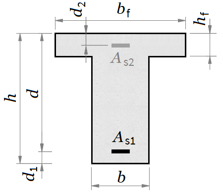
Stem: b = 250 mm, h = 550 mm
Flange: bf = 2400 mm, hf = 140 mm
Concrete cover - c = 30 mm (to bars surface)
Tension reinforcement
Bar count - n1 = 4 with diameter - Φ1 = 20 mm
Reinforcement area - As1 = n1 · π · Φ124 = 4 · 3.14 · 2024 = 1256.64 mm²
Concrete cover to the center of reinforcement - d1 = 45 mm
Effective cross section depth - d = h − d1 = 550 − 45 = 505 mm
Spacing between bar centers - s = 50 mm
Compression reinforcement
Bar count - n2 = 2 with diameter - Φ2 = 8 mm
Reinforcement area - As2 = n2 · π · Φ224 = 2 · 3.14 · 824 = 100.53 mm²
Concrete cover to the center of reinforcement - d2 = 45 mm
Concrete [EN 1992-1-1, Table 3.1]
Characteristic compressive cylinder strength - fck = 25 MPa
Mean value of cylinder compressive strength - fcm = fck + 8 = 25 + 8 = 33 MPa
Mean value of axial tensile strength - fctm = 0.3 · fck23 = 0.3 · 2523 = 2.56 MPa
Secant modulus of elasticity - Ecm = 22 · (fcm10)0.3 = 22 · (3310)0.3 = 31.48 GPa
Steel
Characteristic yield strength - fyk = 500 MPa
Modulus of elasticity - Es = 200 GPa
Ratio of steel to concrete moduli of elasticity - α = EsEcm = 20031.48 = 6.35
[EN 1992-1-1 B.1(1)]
Creep
Relative humidity of the environment - RH = 60 %
Perimeter of cross section in contact with the atmosphere
u = 2 · ( b + h ) = 2 · ( 250 + 550 ) = 1600 mm
Cross section area - Ac = b · h = 250 · 550 = 137500 mm²
Notional size of the cross section
(eq. B.6)
h0 = 2 · Acu = 2 · 1375001600 = 171.88 mm
Relative humidity factor
(eq. B.3a)
φRH = 1 + 1 − RH1000.1 · h00.333 = 1 + 1 − 601000.1 · 171.880.333 = 1.72
Concrete strength factor
(eq. B.4)
βf_cm = 16.8 √ fcm = 16.8 √ 33 = 2.92
Concrete age at the moment of loading - t0 = 28 дни
Concrete age factor
(eq. B.5)
βt0 = 10.1 + t00.2 = 10.1 + 280.2 = 0.488
Notional creep coefficient
(eq. B.2)
φ8_t0 = φRH · βf_cm · βt0 = 1.72 · 2.92 · 0.488 = 2.46
Effective concrete modulus of elasticity
[EN 1992-1-1 §7.4.3(5)]
Ec_eff = Ecm1 + φ8_t0 = 31.481 + 2.46 = 9.1 GPa
Effective ratio of modules of elasticity
[EN 1992-1-1 §7.4.3(6)]
αe = EsEc_eff = 2009.1 = 21.97
[EN 1992-1-1 B.2(1)]
Shrinkage
Coefficient depending on the notional size
kh = 1 − 0.0015 · ( h0 − 100 ) = 1 − 0.0015 · ( 171.88 − 100 ) = 0.892
αds1 = 4 - for cement Class N
αds2 = 0.12 - for cement Class N
(eq. B.12)
βRH = 1.55 · (1 − (RH100)3) = 1.55 · (1 − (60100)3) = 1.22
Basic drying shrinkage strain
(eq. B.11)
εcd0 = 0.85 · ( 220 + 110 · αds1 ) · e-αds2 · fcm10 · 10-6 · βRH = 0.85 · ( 220 + 110 · 4 ) · 2.72-0.12 · 3310 · 10-6 · 1.22 = 0.000459
[EN 1992-1-1 §3.1.4(6)]
Drying shrinkage strain in time
(eq. 3.9)
εcd = kh · εcd0 = 0.892 · 0.000459 = 0.000409
Autogenous shrinkage strain
(eq. 3.11)
εca = 2.5 · ( fck − 10 ) · 10-6 = 2.5 · ( 25 − 10 ) · 10-6 = 3.75×10⁻⁵
Total shrinkage strain
(eq. 3.8)
εcs = εcd + εca = 0.000409 + 3.75×10-5 = 0.000447
Total reinforcement area - As = As1 + As2 = 1256.64 + 100.53 = 1357.17 mm²
Flange area - Af = ( bf − b ) · hf = ( 2400 − 250 ) · 140 = 301000 mm²
T-section area - Ac = b · h + Af = 250 · 550 + 301000 = 438500 mm²
Effective section area
Ared = Ac + αe · As = 438500 + 21.97 · 1357.17 = 468320 mm²
Section modulus about the bottom edge
Sc = b · h22 + Af · (h − hf2) = 250 · 55022 + 301000 · (550 − 1402) = 182292500 mm3
Effective section modulus about the bottom edge
Sred = Sc + αe · ( As1 · d1 + As2 · ( h − d2 ) ) = 182292500 + 21.97 · ( 1256.64 · 45 + 100.53 · ( 550 − 45 ) ) = 184650460 mm3
Effective depth of cross section center
zc = SredAred = 184650460468320 = 394.28 mm
Second moment of area of the concrete section
Ic = b · h3 + ( bf − b ) · hf312 + b · h · (zc − h2)2 + Af · (h − zc − hf2)2 = 250 · 5503 + ( 2400 − 250 ) · 140312 + 250 · 550 · (394.28 − 5502)2 + 301000 · (550 − 394.28 − 1402)2 = 8125757925 mm4
Effective second moment of area for uncracked section
Ired = Ic + αe · ( As1 · ( zc − d1 ) 2 + As2 · ( h − zc − d2 ) 2 ) = 8125757925 + 21.97 · ( 1256.64 · ( 394.28 − 45 ) 2 + 100.53 · ( 550 − 394.28 − 45 ) 2 ) = 11521310457 mm4
Uncracked section properties for SLS
Equivalent bending moment and axial force due to concrete stress about the neutral axis
Nc ( x ) = bf · x22 − ( x − hf ) 2 · ( bf − b ) 2 · ( x > hf )
Equivalent axial force due to internal stress
Nbal ( x ) = Nc ( x ) + αe · ( As2 · ( x − d2 ) − As1 · ( d − x ) )
Depth of neutral axis
x = $Root{Nbal ( x ) = 0; x ∈ [0; h]} = 96.46 mm
Second moment of area for cracked section
Ired_II = bf · x33 + αe · ( As1 · ( d − x ) 2 + As2 · ( x − d2 ) 2 ) = 2400 · 96.4633 + 21.97 · ( 1256.64 · ( 505 − 96.46 ) 2 + 100.53 · ( 96.46 − 45 ) 2 ) = 5332235820 mm4
Characteristic combination
Stress at the bottom edge of the section
σct = Mk · 106Ired · zc = 200 · 10611521310457 · 394.28 = 6.84 MPa
Check for crack opening
σct = 6.84 MPa > fctm = 2.56 MPa - section is cracked
Concrete stress (cracked section)
σc = Mk · 106Ired_II · x = 200 · 1065332235820 · 96.46 = 3.62 MPa
Reinforcement stress (cracked section)
σs1 = αe · Mk · 106Ired_II · ( d − x ) = 21.97 · 200 · 1065332235820 · ( 505 − 96.46 ) = 336.68 MPa
σs2 = -αe · Mk · 106Ired_II · ( x − d2 ) = -21.97 · 200 · 1065332235820 · ( 96.46 − 45 ) = -42.41 MPa
Stress limitation
[EN 1992-1-1 §7.2(2)]
Concrete stress, k1 = 0.6
σc = 3.62 MPa ≤ k1 · fck = 0.6 · 25 = 15 MPa - The condition is satisfied!
[EN 1992-1-1 §7.2(5)]
Reinforcement stress, k3 = 0.8
σs1 = 336.68 MPa ≤ k3 · fyk = 0.8 · 500 = 400 MPa - The condition is satisfied
Quasi-permanent combination
Concrete stress for cracked section
σc = Mqp · 106Ired_II · x = 157 · 1065332235820 · 96.46 = 2.84 MPa
[EN 1992-1-1 §7.2(3)]
Stress limitation, k2 = 0.45
σc = 2.84 MPa ≤ k2 · fck = 0.45 · 25 = 11.25 MPa - The condition is satisfied!
Non-linear creep is NOT calculated!
[EN 1992-1-1 §7.3.2(2)]
Minimum reinforcement area
Allowable reinforcement stress - σs = fyk = 500 MPa
Approximate value of axial tensile strength - fct_eff = fctm = 2.56 MPa
Area of tensile zone before opening of first crack
Act = b · zc = 250 · 394.28 = 98570.7 mm²
k = 1 − 0.35 · ( h − 300 ) 500 = 1 − 0.35 · ( 550 − 300 ) 500 = 0.825 - for 300 < h < 800
kc = 0.4
h1 = h = 550 - for h ≤ 1000
Minimum reinforcement
As_min = kc · k · fct_eff · Actσs = 0.4 · 0.825 · 2.56 · 98570.7500 = 166.87 mm²
As1 = 1256.64 mm² ≥ As_min = 166.87 mm² - The condition is satisfied!
Calculation of crack widths
[EN 1992-1-1 §7.3.2(3)]
Depth of the effective area
hc_eff = min(2.5 · ( h − d ) ; min(h − x3; h2)) = min(2.5 · ( 550 − 505 ) ; min(550 − 96.463; 5502)) = 112.5 mm
Concrete effective area within tensile zone
Ac_eff = b · hc_eff = 250 · 112.5 = 28125 mm²
ρp_eff = As1Ac_eff = 1256.6428125 = 0.0447
[EN 1992-1-1 §7.3.4(3)]
For s = 50 mm ≤ 5 · (c + Φ12) = 5 · (30 + 202) = 200 mm:
k1 = 0.8 - for high bond bars
k2 = 0.5 - for bending
k3 = 3.4 , k4 = 0.425
Maximum final crack spacing
sr_max = k3 · c + k1 · k2 · k4 · Φ1ρp_eff = 3.4 · 30 + 0.8 · 0.5 · 0.425 · 200.0447 = 178.1 mm
The check is performed for quasi-permanent combination
Reinforcement stress
σs = αe · Mqp · 106Ired_II · ( d − x ) = 21.97 · 157 · 1065332235820 · ( 505 − 96.46 ) = 264.3 MPa
Long-term load factor - kt = 0.4
[EN 1992-1-1 §7.3.4(2)]
Difference between mean values of concrete and reinforcement strains
εsm - εcm = Δε = max(σs − kt · fct_effρp_eff · ( 1 + α · ρp_eff ) ; 0.6 · σs)Es · 103 = max(264.3 − 0.4 · 2.560.0447 · ( 1 + 6.35 · 0.0447 ) ; 0.6 · 264.3)200 · 103 = 0.00117
[EN 1992-1-1 §7.3.4(1)]
Crack widths
wk = sr_max · Δε = 178.1 · 0.00117 = 0.209 mm
[EN 1992-1-1 §7.3.1(5)]
Limiting crack width value
[EN 1992-1-1, Table NA.4]
wmax = 0.4 mm - for exposure classes X0, XC1
Crack width limitation
wk = 0.209 mm ≤ wmax = 0.4 mm - The condition is satisfied!
Crack opening moment
Mcr = fctm · Iredzc · 10-6 = 2.56 · 11521310457394.28 · 10-6 = 74.95 kNm
Coefficient for duration of loads
β = 0.5 - for long-term loads
[EN 1992-1-1 §7.4.3(3)]
Distribution coefficient
ζ = 1 − β · (McrMqp)2 = 1 − 0.5 · (74.95157)2 = 0.886 - for cracked section
Calculation of curvature
First moment of reinforcement area about centroid of uncracked section
S = As1 · ( zc − d1 ) − As2 · ( h − zc − d2 ) = 1256.64 · ( 394.28 − 45 ) − 100.53 · ( 550 − 394.28 − 45 ) = 427791 mm3
Curvature due to shrinkage of uncracked section
[EN 1992-1-1 §7.4.3(6)]
θcs_I = εcs · αe · SIred = 0.000447 · 21.97 · 42779111521310457 = 3.65×10⁻⁷
Curvature of uncracked section
θI = MqpEc_eff · Ired · 103 + θcs_I = 1579.1 · 11521310457 · 103 + 3.65×10-7 = 1.86×10⁻⁶
First moment of reinforcement area about centroid of cracked section
S = As1 · ( d − x ) − As2 · ( x − d2 ) = 1256.64 · ( 505 − 96.46 ) − 100.53 · ( 96.46 − 45 ) = 508208 mm3
Curvature due to shrinkage of cracked section
[EN 1992-1-1 §7.4.3(6)]
θcs_II = εcs · αe · SIred_II = 0.000447 · 21.97 · 5082085332235820 = 9.36×10⁻⁷
Curvature of cracked section
θII = MqpEc_eff · Ired_II · 103 + θcs_II = 1579.1 · 5332235820 · 103 + 9.36×10-7 = 4.17×10⁻⁶
Total curvature
[EN 1992-1-1 §7.4.3(3)]
θ = ζ · θII + ( 1 − ζ ) · θI = 0.886 · 4.17×10-6 + ( 1 − 0.886 ) · 1.86×10-6 = 3.91×10⁻⁶
Factor considering the static scheme
k = 548 = 0.104 - for simply supported beam with uniformly distributed load
Deflection due to quasi-permanent combination - δ = k · θ · L2 · 106 = 0.104 · 3.91×10-6 · 5.752 · 106 = 13.46 mm
[EN 1992-1-1 §7.4.1(4)]
Maximum deflection - δmax = L · 103250 = 5.75 · 103250 = 23 mm
Deflection check:
δ = 13.46 mm ≤ δmax = 23 mm - The condition is satisfied!
Shear Design of Rectangular Section¶
Shear design of a rectangular section under EN 1992-1-1: shear strength without links \(V_{Rd,c}\), required link area for a strut angle \(\theta\) and check of the maximum strut compression.
'<small>According to <strong>Eurocode</strong>: EN 1992-1-1</small>
'<div style="max-width:180mm;">
'<img class="side" style="width:270pt;" src="../../Images/structures/rc/design/beam-shear.png" alt="beam-shear.png">
'<h4>Cross section dimensions</h4>
'Width -'b = ?'mm, Height'h = ?'mm
#post
'Cross section area -'A_c = b*h'mm²
#show
'Tensile reinforcement area -'A_sl = ?'mm²
'Effective depth -'d = h - ?'mm
#post
'Reinforcement ratio -'ρ_l = min(A_sl/(b*d); 0.02)
#show
'Shear links diameter -'d_w = ?'mm
'Number of legs for one link -'n_w = ?
'<p><b>Section design loads</b></p>
'Shear force -'V_Ed = ?'kN  Axial force -'N_Ed = ?'kN
'<h4>Material properties</h4>
'<p class="ref">[EN 1992-1-1, Table 3.1]</p>
'<p><b>Concrete</b></p>
'Characteristic compressive cylinder strength -'f_ck = ?'MPa
'Partial safety factor for concrete -'γ_c = 1.5','α_cc = ?
#post
'Design compressive cylinder strength -'f_cd = α_cc*f_ck/γ_c'MPa
#show
'<p><b>Steel for shear reinforcement</b></p>
'Characteristic yield strength -'f_yk = ?'MPa
#post
'Partial safety factor for steel -'γ_s = 1.15
'Design yield strength -'f_ywd = f_yk/γ_s'MPa
'
'<div class="fold">
'<h4>Shear capacity without reinforcement<small class="ref">[EN 1992-1-1, § 6.2.2]</small></h4>
k = min(1 + sqr(200/d); 2)
'Stress due to axial force (N<sub>Ed</sub> > 0 for compression)
σ_cp_ = N_Ed*10^3/A_c'MPa
'Maximum stress value:'0.2*f_cd'MPa
σ_cp = min(σ_cp_;0.2*f_cd)'MPa
C_Rd_c = 0.18/γ_c
v_min = 0.035*k^(3/2)*sqr(f_ck)
k_1 = 0.15
'<p class="ref">(6.2a)</p>
'Shear resistance
V_Rd_c_ = (C_Rd_c*k*(100*ρ_l*f_ck)^(1/3) + k_1*σ_cp)*b*d*10^-3'kN
'Minimum shear resistance
'<p class="ref">(6.2b)</p>
V_Rd_c_min = (v_min + k_1*σ_cp)*b*d*10^-3'kN
V_Rd_c = max(V_Rd_c_min;V_Rd_c_)'kN
'Design check
'</div>
#if V_Ed ≤ V_Rd_c
V_Ed'kN ≤'V_Rd_c'kN. Shear reinforcement is NOT required by calculation!
#else
V_Ed'kN >'V_Rd_c'kN. Shear reinforcement is required!
'<div class="fold">
'<h4>Shear capacity with reinforcement <small class="ref">[EN 1992-1-1, §6.2.3]</small></h4>
'Lever arm of internal forces -'z = 0.9*d'mm
'<p class="ref">(6.6N)</p>
ν_1 = 0.6*(1 - f_ck/250)
k_σ = σ_cp_/f_cd
'Factor α<sub>cw</sub> depends on the value of k<sub>σ</sub>
#if k_σ < 0.25
α_cw = 1 + k_σ'for 0 < <i>k</i><sub>σ</sub> < 0.25
#else if k_σ < 0.5
α_cw = 1.25'for 0.25 < <i>k</i><sub>σ</sub> < 0.5
#else if k_σ < 1
α_cw = 2.5*(1 - k_σ)'for 0.5 < <i>k</i><sub>σ</sub> < 1
#else
'<p class="err">The value for σ<sub>cp</sub>is NOT admissible</p>
#end if
'<p class="ref">(6.9)</p>
'Maximum shear capacity at θ = 45°
V_Rd_max_45 = α_cw*b*z*ν_1*f_cd/2*10^-3'kN
#if V_Ed ≤ V_Rd_max_45
V_Ed'kN ≤'V_Rd_max_45'kN. The check is satisfied!
'Angle of concrete struts
θ_ = 0.5*asin(V_Ed/V_Rd_max_45)'°
'<p class="ref">(6.7N)</p>
'The angle is limited between 21,8° ≤ θ ≤ 45°(1 ≤ cot(θ) ≤ 2.5)
θ = max(21.8;min(θ_;45))'°
'<p class="ref">(6.9)</p>
'Bearing capacity check at'θ'°
V_Rd_max = α_cw*b*z*ν_1*f_cd/(cot(θ) + tan(θ))*10^-3'kN
'</div>
'Design check:'V_Ed'kN ≤'V_Rd_max'kN
'<p class="ref">(6.8)</p>
'Required shear reinforcement area
A_sw = V_Ed*10^6/(z*f_ywd*cot(θ))'mm²/m'
'Shear links with'n_w'legs and diameter -'d_w'mm are provided
'Area of one leg -'A_s1 = π*(d_w/2)^2'mm²
'Required links spacing -'s = 1000*n_w*A_s1/A_sw'mm
'<p class="ref">[EN 1992-1-1, §9.2.2]</p>
'Maximum spacing -'s_max = min(0.75*d;300)'mm
#if s > s_max
s'mm >'s_max'mm. Spacing is greater than the maximum.
'The relevant spacing is accepted:'s = s_max'mm
#end if
'<p class="ref">(9.4)</p>
'Reinforcement ratio
ρ_w = A_sw/(s*b)
'<p class="ref">(9.5N)</p>
ρ_w_min = 0.08*sqr(f_ck)/f_yk
#if ρ_w < ρ_w_min
ρ_w'<'ρ_w_min'. Reinforcement ratio is lower than the minimum. Minimum reinforcement ratio is accepted.
#end if
'<p class="ref">(6.18)</p>
'Additional force in tensile reinforcement
ΔF_td = 0.5*V_Ed*cot(θ)'kN
'<p class="ref">(9.2)</p>
'Bending moment diagram shifting distance
a_l = z*cot(θ)/2'mm
#else
'</div>
V_Ed'kN >'V_Rd_max_45'kN
'<p class="err">The check is NOT satisfied!. Increase cross section dimensions or concrete grade.</p>
#end if
#end if
#show
'</div>
300 800 1200 50 8 2 600 0 20 1 500
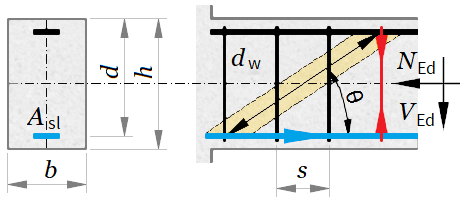
Width - b = 300 mm, Height h = 800 mm
Cross section area - Ac = b · h = 300 · 800 = 240000 mm²
Tensile reinforcement area - Asl = 1200 mm²
Effective depth - d = h − 50 = 800 − 50 = 750 mm
Reinforcement ratio - ρl = min(Aslb · d; 0.02) = min(1200300 · 750; 0.02) = 0.00533
Shear links diameter - dw = 8 mm
Number of legs for one link - nw = 2
Section design loads
Shear force - VEd = 600 kN Axial force - NEd = 0 kN
[EN 1992-1-1, Table 3.1]
Concrete
Characteristic compressive cylinder strength - fck = 20 MPa
Partial safety factor for concrete - γc = 1.5 , αcc = 1
Design compressive cylinder strength - fcd = αcc · fckγc = 1 · 201.5 = 13.33 MPa
Steel for shear reinforcement
Characteristic yield strength - fyk = 500 MPa
Partial safety factor for steel - γs = 1.15
Design yield strength - fywd = fykγs = 5001.15 = 434.78 MPa
k = min(1 + 200d; 2) = min(1 + 200750; 2) = 1.52
Stress due to axial force (NEd > 0 for compression)
σcp_ = NEd · 103Ac = 0 · 103240000 = 0 MPa
Maximum stress value: 0.2 · fcd = 0.2 · 13.33 = 2.67 MPa
σcp = min ( σcp_; 0.2 · fcd ) = min ( 0; 0.2 · 13.33 ) = 0 MPa
CRd_c = 0.18γc = 0.181.5 = 0.12
vmin = 0.035 · k32 · √ fck = 0.035 · 1.5232 · √ 20 = 0.292
k1 = 0.15
(6.2a)
Shear resistance
VRd_c_ = ( CRd_c · k · ( 100 · ρl · fck ) 13 + k1 · σcp ) · b · d · 10-3 = ( 0.12 · 1.52 · ( 100 · 0.00533 · 20 ) 13 + 0.15 · 0 ) · 300 · 750 · 10-3 = 90.13 kN
Minimum shear resistance
(6.2b)
VRd_c_min = ( vmin + k1 · σcp ) · b · d · 10-3 = ( 0.292 + 0.15 · 0 ) · 300 · 750 · 10-3 = 65.76 kN
VRd_c = max ( VRd_c_min; VRd_c_ ) = max ( 65.76; 90.13 ) = 90.13 kN
Design check
VEd = 600 kN > VRd_c = 90.13 kN. Shear reinforcement is required!
Lever arm of internal forces - z = 0.9 · d = 0.9 · 750 = 675 mm
(6.6N)
ν1 = 0.6 · (1 − fck250) = 0.6 · (1 − 20250) = 0.552
kσ = σcp_fcd = 013.33 = 0
Factor αcw depends on the value of kσ
αcw = 1 + kσ = 1 + 0 = 1 for 0 < kσ < 0.25
(6.9)
Maximum shear capacity at θ = 45°
VRd_max_45 = αcw · b · z · ν1 · fcd2 · 10-3 = 1 · 300 · 675 · 0.552 · 13.332 · 10-3 = 745.2 kN
VEd = 600 kN ≤ VRd_max_45 = 745.2 kN. The check is satisfied!
Angle of concrete struts
θ_ = 0.5 · asin(VEdVRd_max_45) = 0.5 · asin(600745.2) = 26.81 °
(6.7N)
The angle is limited between 21,8° ≤ θ ≤ 45°(1 ≤ cot(θ) ≤ 2.5)
θ = max ( 21.8; min ( θ_; 45 ) ) = max ( 21.8; min ( 26.81; 45 ) ) = 26.81 °
(6.9)
Bearing capacity check at θ = 26.81 °
VRd_max = αcw · b · z · ν1 · fcdcot ( θ ) + tan ( θ ) · 10-3 = 1 · 300 · 675 · 0.552 · 13.33cot ( 26.81 ) + tan ( 26.81 ) · 10-3 = 600 kN
Design check: VEd = 600 kN ≤ VRd_max = 600 kN
(6.8)
Required shear reinforcement area
Asw = VEd · 106z · fywd · cot ( θ ) = 600 · 106675 · 434.78 · cot ( 26.81 ) = 1033.28 mm²/m
Shear links with nw = 2 legs and diameter - dw = 8 mm are provided
Area of one leg - As1 = π · (dw2)2 = 3.14 · (82)2 = 50.27 mm²
Required links spacing - s = 1000 · nw · As1Asw = 1000 · 2 · 50.271033.28 = 97.29 mm
[EN 1992-1-1, §9.2.2]
Maximum spacing - smax = min ( 0.75 · d; 300 ) = min ( 0.75 · 750; 300 ) = 300 mm
(9.4)
Reinforcement ratio
ρw = Asws · b = 1033.2897.29 · 300 = 0.0354
(9.5N)
ρw_min = 0.08 · √ fckfyk = 0.08 · √ 20500 = 0.000716
(6.18)
Additional force in tensile reinforcement
ΔFtd = 0.5 · VEd · cot ( θ ) = 0.5 · 600 · cot ( 26.81 ) = 593.58 kN
(9.2)
Bending moment diagram shifting distance
al = z · cot ( θ ) 2 = 675 · cot ( 26.81 ) 2 = 667.77 mm
Spotted an error? Edit these examples.